
High rate, continuous deposition of high quality amorphous, nanocrystalline, microcrystalline or polycrystalline materials

a technology of nanocrystalline materials and high-quality amorphous materials, applied in the direction of chemical vapor deposition coating, plasma technique, coating, etc., can solve the problem that the rate at which photovoltaic materials can be formed cannot meet the the material produced through plasma deposition process cannot achieve economic competitiveness with fossil fuels in terms of cost per unit of energy, and the rate at which photovoltaic materials can be formed cannot achieve competitive materials. , high, commercially significan

Inactive Publication Date: 2008-04-17
ENERGY CONVERSION DEVICES INC
View PDF5 Cites 25 Cited by
  • Summary
  • Abstract
  • Description
  • Claims
  • Application Information

AI Technical Summary

Benefits of technology

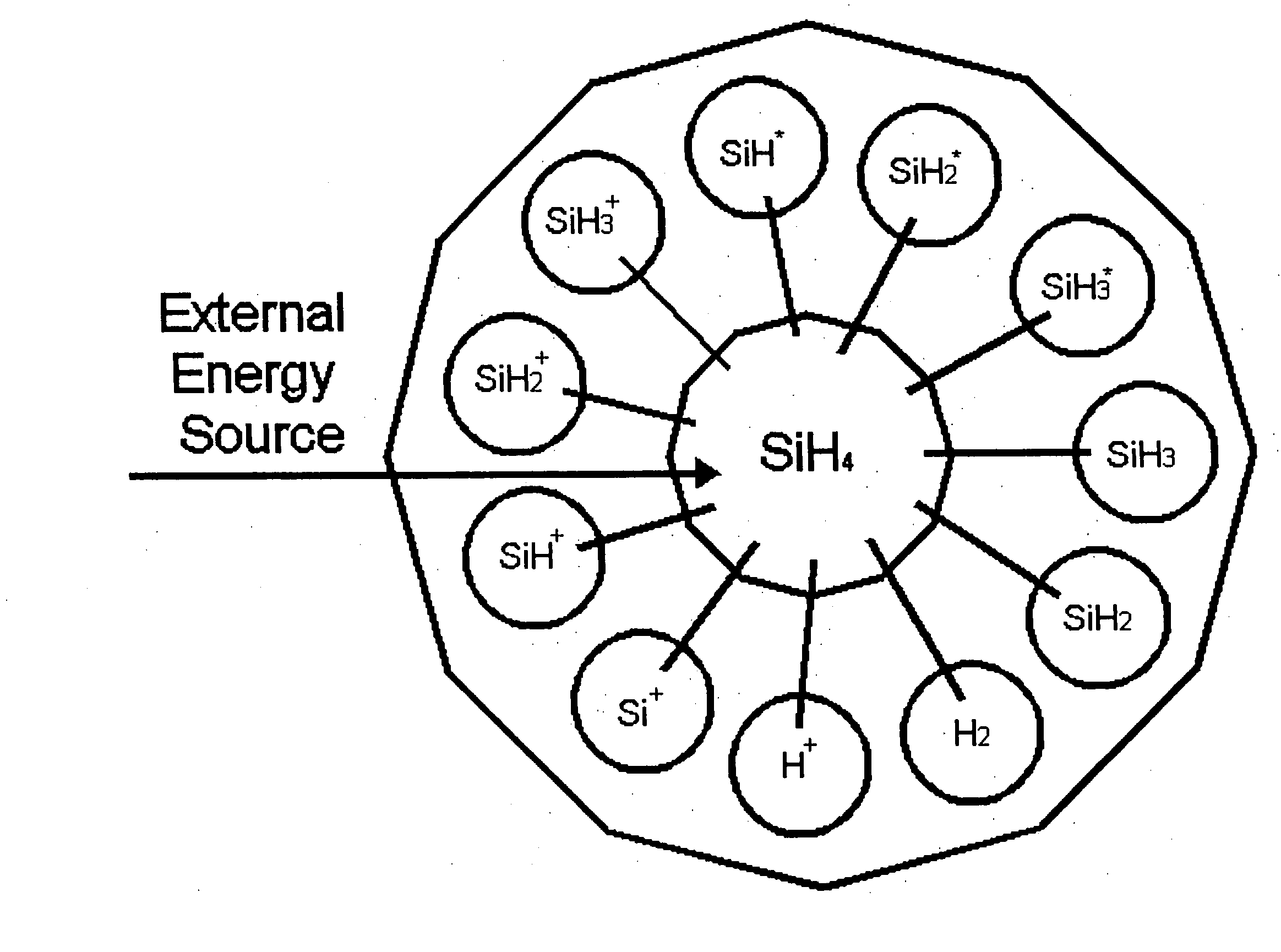
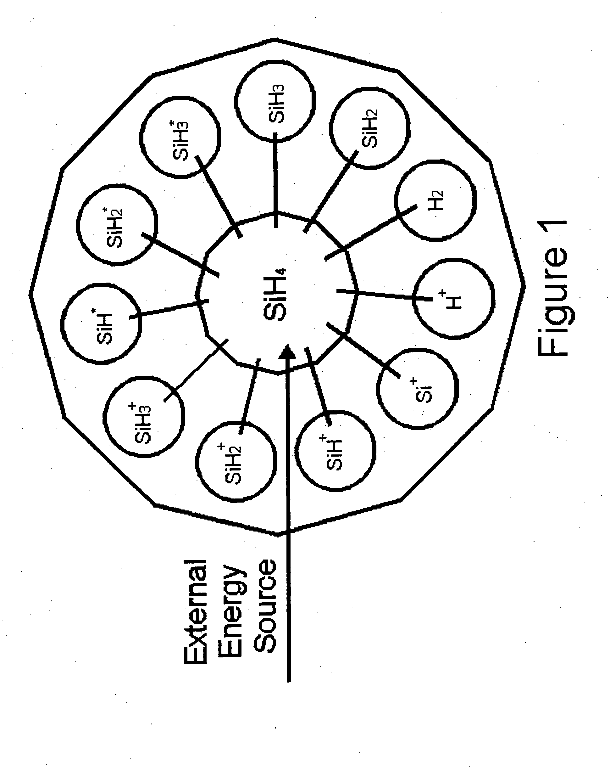
The present invention describes how to create high-quality thin films made up of different forms of crystal structures such as amorphous, nanocrystalline, microcrystalline, or polycrystalline materials. This can be done by first creating a source of active particles from a gas and then allowing these particles to collide with a precursor gas containing a target substance for deposition. By doing this, we are able to produce large amounts of pure deposition species without actually creating a plasma inside the colliding regions. Using this technique, it becomes possible to achieve exceptionally fast rates of deposition on various surfaces while maintaining excellent quality of the resulting films.

Problems solved by technology

The technical problem addressed in this patent text is the deterioration of the quality of silicon alloy materials deposited using plasma enhanced chemical vapor deposition (PECVD) due to the uncontrollable chemistry provided by the plasma. The text discusses the problem of gas phase nucleation and powder formation in the plasma. The patent aims to address this problem by controlling the plasma to generate only the desired free radical or ionic species, which can lead to higher quality electronic properties of the deposited material. The text also describes the development of a process and apparatus that can deposit high quality materials at high rates, particularly on a continuous roll-to-roll basis.

Method used


Image

  • High rate, continuous deposition of high quality amorphous, nanocrystalline, microcrystalline or polycrystalline materials
  • High rate, continuous deposition of high quality amorphous, nanocrystalline, microcrystalline or polycrystalline materials
  • High rate, continuous deposition of high quality amorphous, nanocrystalline, microcrystalline or polycrystalline materials

Examples


Embodiment Construction

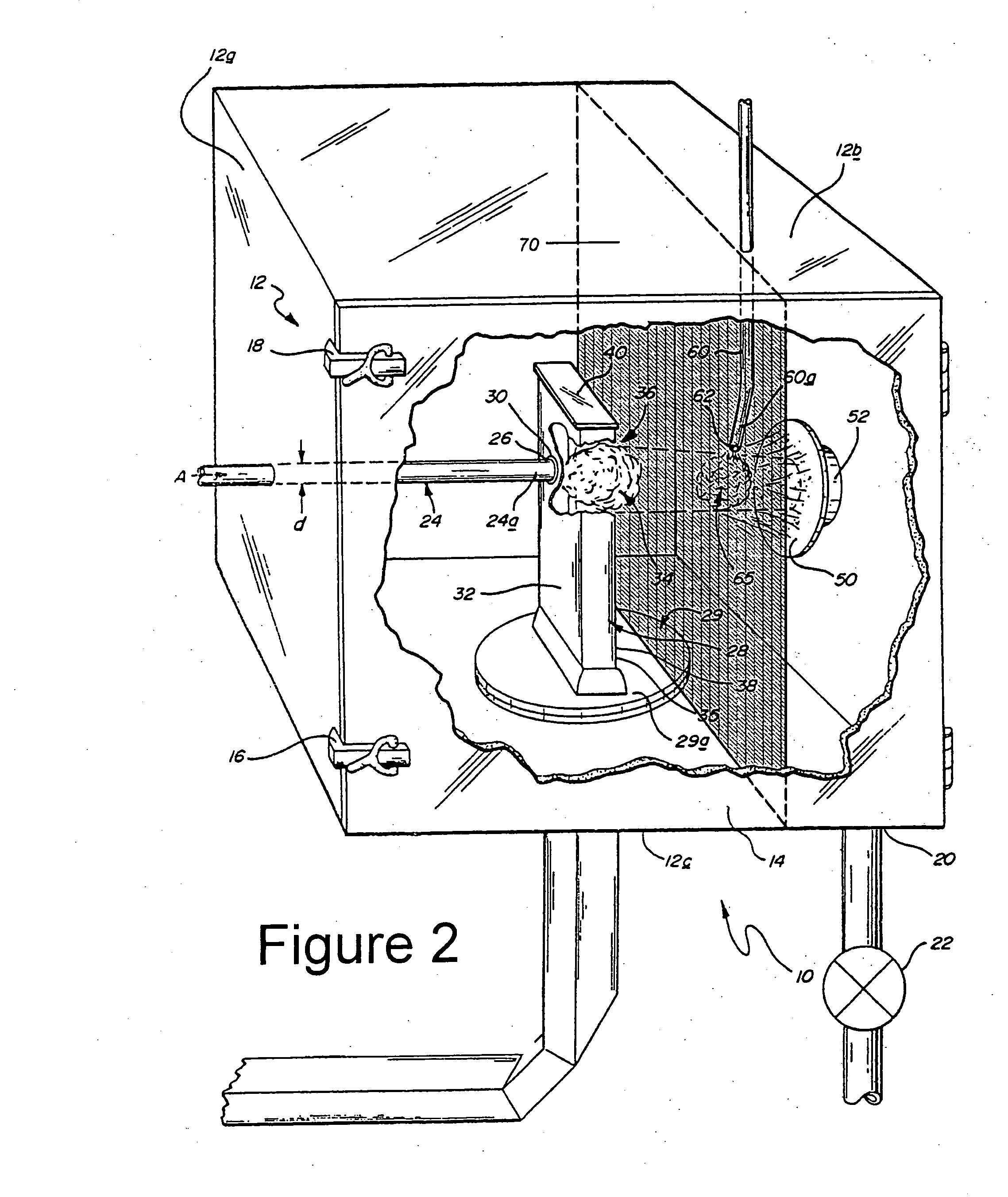
[0041]Referring now to the drawings and particularly to FIG. 2, there is illustrated therein a perspective view, partially cut-away, of a reaction apparatus, generally referenced by the numeral 10. Functionally, the apparatus 10 is adapted to generate a plume of activated species from an energy transferring gas introduced into the interior thereof. The activated species of the energy transferring gas may then be directed towards a region populated by a high density of a precursor deposition gas, whereby neutral free radicals of the activated species after being separated from the ions of the activated species collide with the precursor deposition gas so as to form desired energized deposition species. These energized deposition species will subsequently deposit relatively high quality, thin film layers of silicon, germanium, carbon and combinations thereof, upon a substrate operatively disposed in proximate relationship to the collision region.

[0042]The apparatus 10 as depicted in F...


PUM

PropertyMeasurementUnit
Fractionaaaaaaaaaa
Fractionaaaaaaaaaa
Fractionaaaaaaaaaa

Abstract

An apparatus and a method for high rate deposition of thin film materials. The method including the steps of (1) generating a supply of activated species from an energy transferring gas, through the use of a plasma; (2) separating the charged species from the non-charged species of the activated species (optionally through the use of an electrically biased screen or mesh), (3) transporting the non-charged species to a collision region (through the use of the substantial pressure differential and transonic velocity of the energy transferring gas); (4) introducing a precursor deposition feedstock gas into the collision region and; (5) producing large quantities of desirable deposition species within said collision region via the collision of non-charged species of said energy transferring gas with molecules within the precursor deposition feedstock gas; and (6) depositing, at a high deposition rate, quality thin film material onto a substrate which is adjacent to the collision. The apparatus will allow for the formation of a filtered, neutralized plasma from which non-single crystal semiconductors having fewer than 5.0×10¹⁴/cm3 subgap defects.

Description


Claims


Application Information

Patent Timeline
Owner ENERGY CONVERSION DEVICES INC
Learn More