
Storage medium drive

a storage medium and drive technology, applied in the field of storage medium drives, can solve the problems of affecting the performance of the drive, the deterioration of the head slider positioning, and the inability to adjust the drive, so as to reduce the vibration, reduce the vibration, and prevent the effect of nois

Inactive Publication Date: 2008-04-17
TOSHIBA STORAGE DEVICE CORP
View PDF9 Cites 2 Cited by
  • Summary
  • Abstract
  • Description
  • Claims
  • Application Information

AI Technical Summary

Benefits of technology

[0008] It is accordingly an object of the present invention to provide a storage medium drive capable of preventing vibrations and noises.
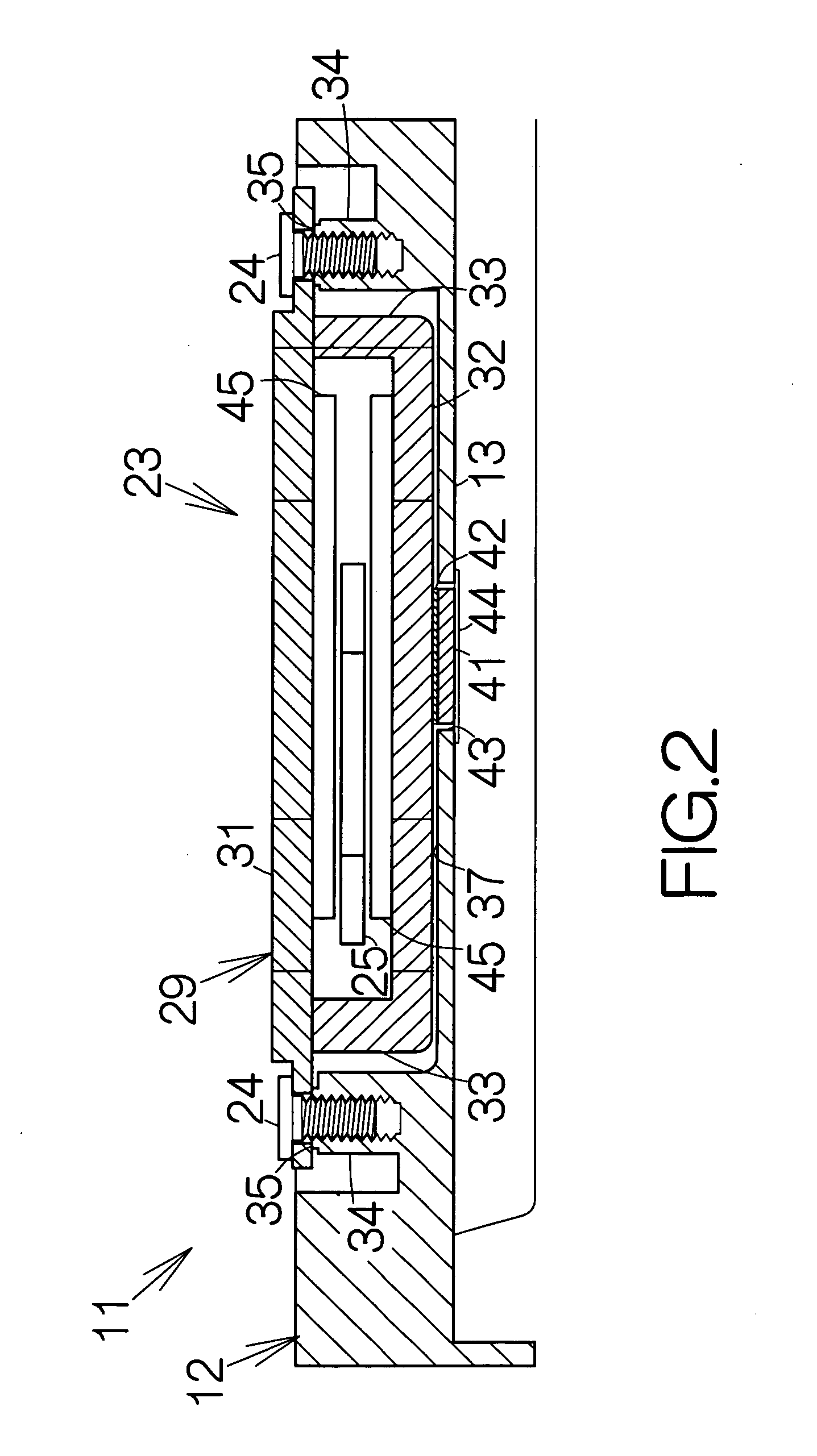
[0010] The displacement of the coil causes the head carriage to swing at a high speed in the storage medium drive. The coil moves along an imaginary plane. A reaction is applied to the first yoke member and the second yoke member during the displacement of the coil. Such a reaction causes vibrations in the first yoke member and the second yoke member in parallel with the imaginary plane. Simultaneously, the vibrations of the first yoke member and the second yoke member serve to induce the vibrations of the weight in parallel with the imaginary plane. The elastic adhesive member serves to establish a shift in phase between the vibrations in the first and second yoke members and the vibrations of the weight. The vibrations in the opposite directions counteract each other, so that the vibrations are significantly reduced in the upper and lower yoke members. Reduced vibrations lead to prevention of noises. No vibration is transferred to the head carriage through the support body.
[0011] The weight may be received in a through hole penetrating through the support body in the storage medium drive. In this case, the addition of the weight will not hinder achievement of a reduced thickness of the storage medium drive. A predetermined gap is intentionally formed between the outer periphery of the weight and the wall surface of the through hole. The gap reliably enables movement of the weight within the through hole. This leads to a reliably prevention of vibrations in the upper yoke member and the lower yoke member. Noises are reliably prevented. Moreover, the weight can be attached to the outward surface of the second yoke member through the through hole from the outside of the support body. Since the weight is in this manner attached to the second yoke member, the weight can be positioned at a designed position on the second yoke member with a high accuracy by utilizing the relative position between the through hole and the second yoke member. The elastic adhesive member may be made of a viscoelastic material in the storage medium drive. The elastic adhesive member exhibits viscoelasticity.

Problems solved by technology

When the voice coil is driven to move at a high speed, vibrations are inevitably induced in the yoke members as a reaction, for example.
The head actuator thus suffers from a deteriorated positioning of a head slider.
The induced vibrations cause noises in the yoke members and the base.

Method used


Image

  • Storage medium drive
  • Storage medium drive
  • Storage medium drive

Examples


Embodiment Construction

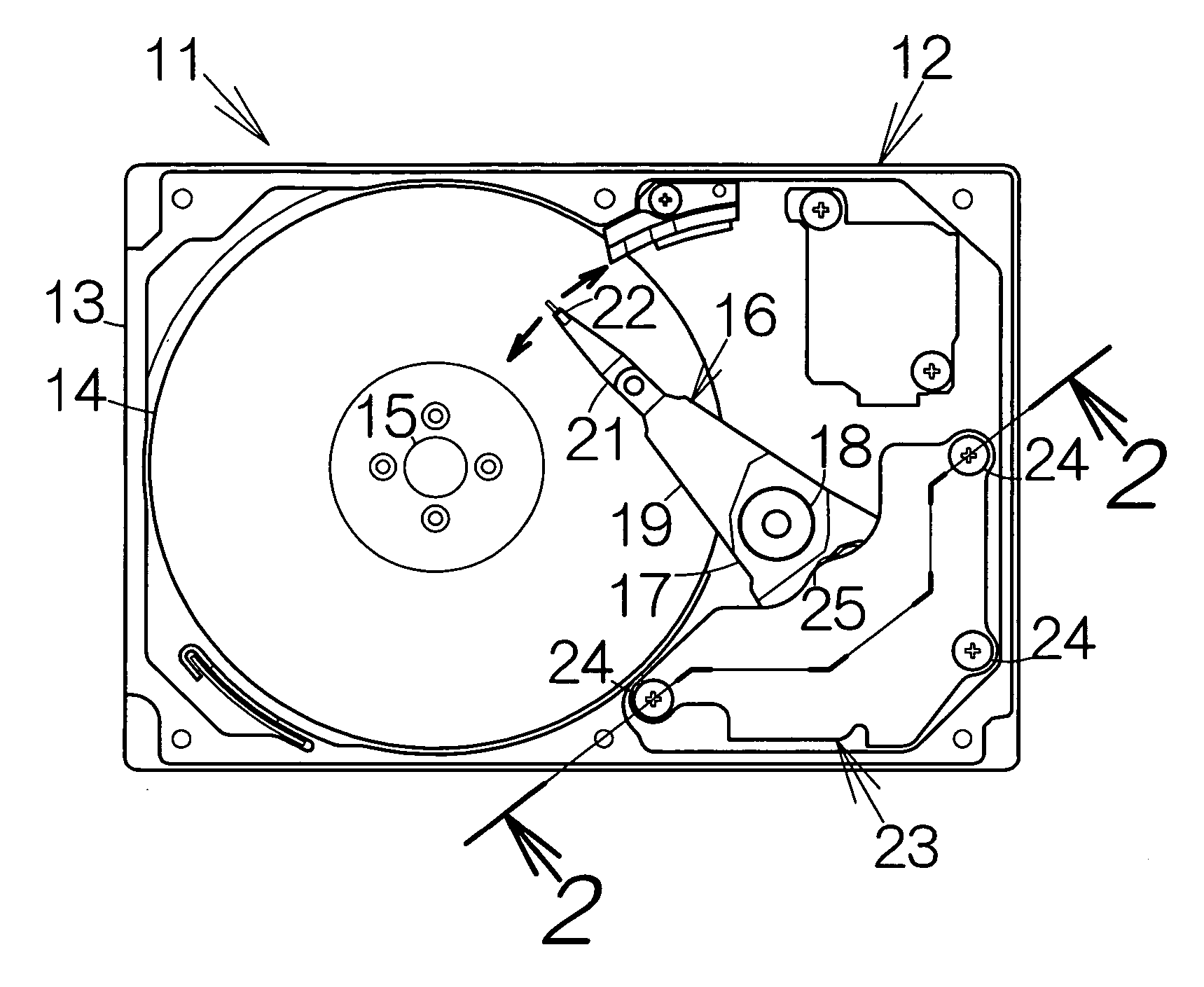
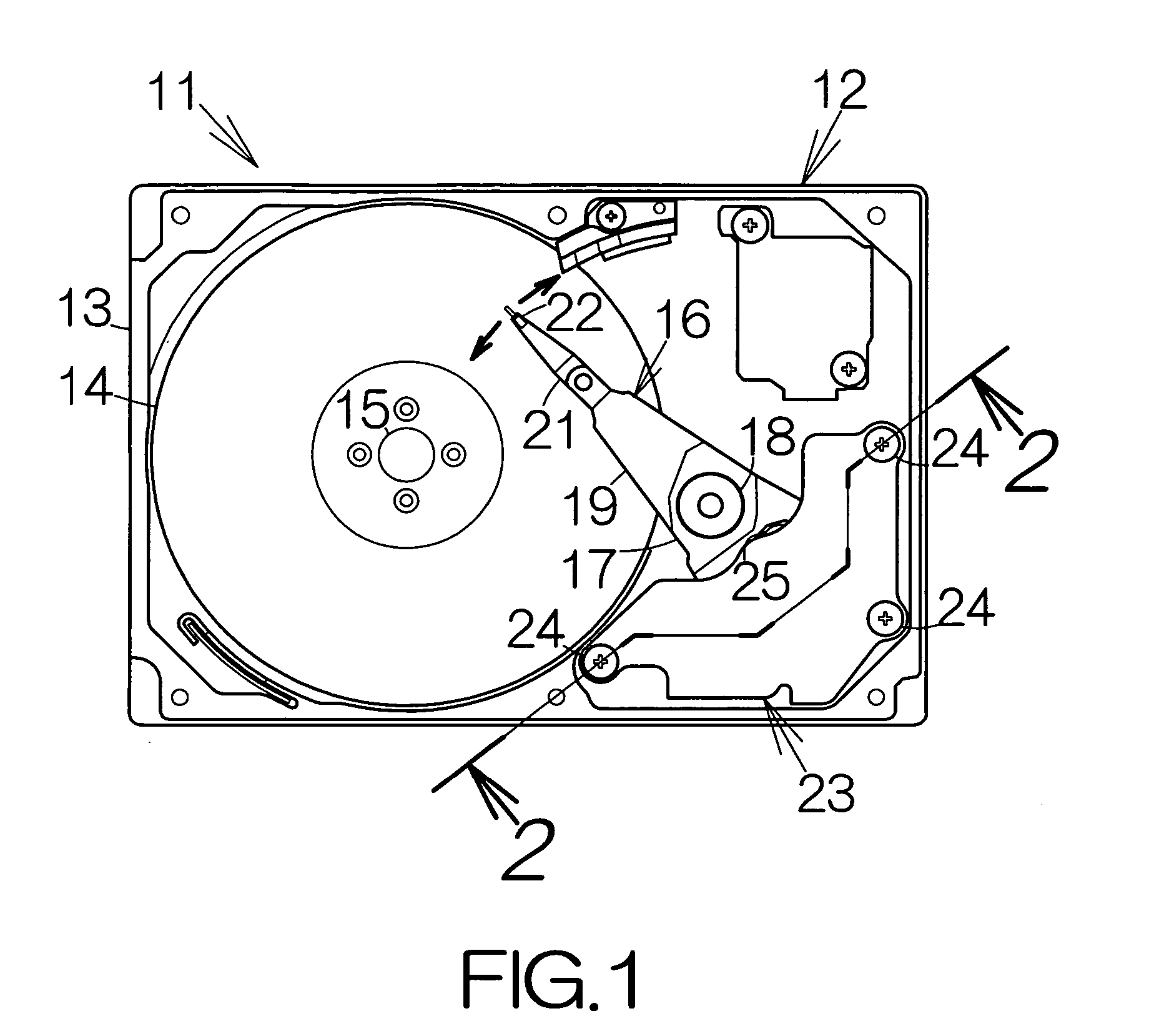
[0015]FIG. 1 schematically illustrates a hard disk drive, HDD, 11 as an example of a storage medium drive or a storage device according to the present invention. The hard disk drive 11 includes a box-shaped enclosure 12 including an open box-shaped support body, namely a base 13. The base 13 defines an inner space in the form of a flat parallelepiped, for example. The base 13 may be made of a metallic material such as aluminum, for example. Molding process may be employed to form the base 13.

[0016] An enclosure cover, not shown, is coupled to the opening of the base 13. The enclosure cover serves to establish an airtight inner space of the base 13 between the base 13 and the enclosure cover itself. Pressing process may be employed to form the enclosure cover out of a plate material, for example. A metallic plate made of aluminum may be employed as the plate material, for example. Alternatively, the plate material may be a layered material, for example.

[0017] At least one magnetic ...


PUM


Abstract

A head actuator includes first and second yoke members. An elastic adhesive member is coupled to the second yoke member. A weight is coupled to the elastic adhesive member. The displacement of a coil in the head actuator causes a carriage to swing. The displacement of the coil generates a reaction. Such a reaction causes vibrations in the first yoke member and the second yoke member. Simultaneously, the vibrations of the first yoke member and the second yoke member serve to induce the vibrations of the weight. The elastic adhesive member serves to establish a shift in phase between the vibrations in the first and second yoke members and the vibrations of the weight. The vibrations in the opposite directions counteract each other, so that the vibrations are significantly reduced in the upper and lower yoke members.

Description

[0001] This is a continuation filed under 35 U.S.C. § 111(a), of International Application No. PCT / JP2005 / 010513, filed Jun. 8, 2005.BACKGROUND OF THE INVENTION [0002] 1. Field of the Invention [0003] The present invention relates to a storage medium drive, such as a hard disk drive, including a voice coil motor, for example. [0004] 2. Description of the Prior Art: [0005] A head actuator is incorporated in a hard disk drive. A carriage is coupled to a voice coil motor, VCM, in the head actuator. The voice coil motor includes upper and lower yoke members made of a magnetic material. The upper and lower yoke members are coupled to each other. The upper yoke member is received on bosses standing upright from a base. The upper yoke member is screwed to the bosses. A predetermined gap is defined between the lower yoke member and the base. [0006] A voice coil is placed in a space between the upper and lower yoke members. The voice coil is coupled to the carriage. Magnetic flux circulates ...

Claims


Application Information

Patent Timeline
IPC IPC(8): G11B5/012
CPCG11B21/02G11B5/5569
Inventor KOMURA, YUKIHIRO
Owner TOSHIBA STORAGE DEVICE CORP
Learn More