
Spatially offset multi-imager-panel architecture for projecting an image

a multi-imager and image technology, applied in the field of display systems, can solve the problems of non-linear increase of the cost of a spatial light modulator, a limiting factor in the cost-effective production of such systems, and the significant cost of digital projection systems such as dmd panels

Active Publication Date: 2008-04-17
MIRADIA INC
View PDF61 Cites 27 Cited by
  • Summary
  • Abstract
  • Description
  • Claims
  • Application Information

AI Technical Summary

Problems solved by technology

A significant cost of digital projection systems is the spatial light modulator, such as a DMD panel.
For higher-resolution digital projection systems, which require more pixels to provide a higher-resolution image, spatial light modulator cost is a limiting factor in the cost-effective production of such systems.
This is because the cost of a spatial light modulator increases non-linearly as the resolution of the spatial light modulator is increased.
In either case, wobulation relies on the precise mechanical displacement of a digital projection system component that takes place at very high speed, and such high-speed mechanical displacement is subject to drift, misalignment, non-linear behavior, and other issues that can affect image quality.
In addition, a digital projection system using wobulation requires control electronics and image processing drivers having substantially greater bandwidth than a digital system displaying the same resolution image without the use of wobulation.

Method used


Image

  • Spatially offset multi-imager-panel architecture for projecting an image
  • Spatially offset multi-imager-panel architecture for projecting an image
  • Spatially offset multi-imager-panel architecture for projecting an image

Examples


Embodiment Construction

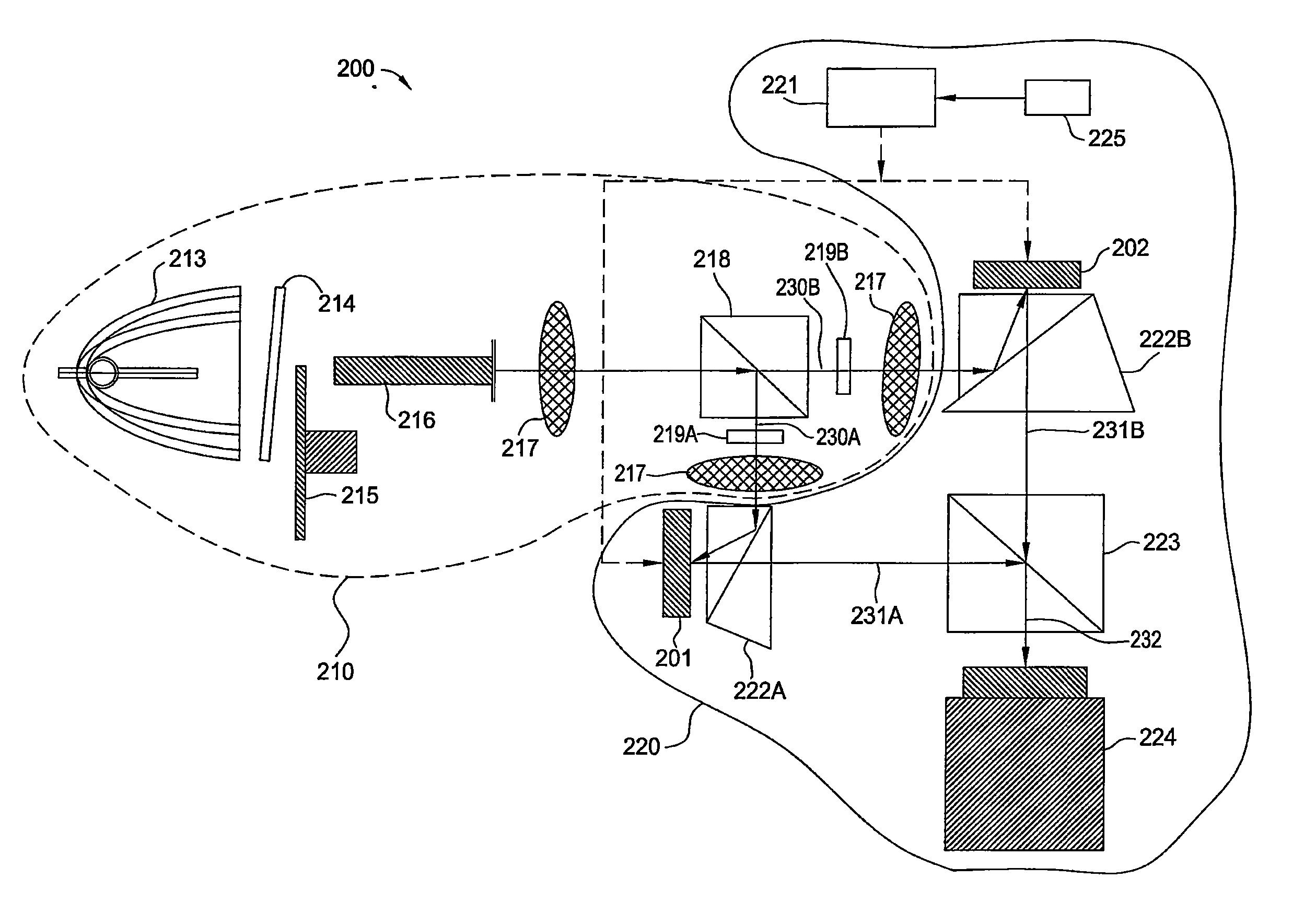
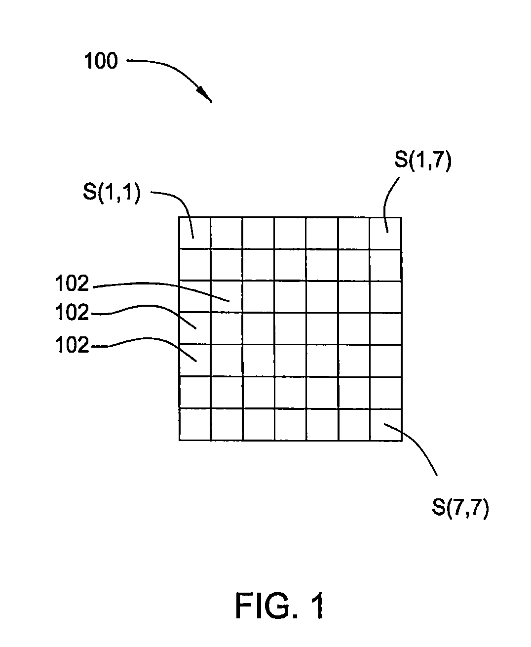
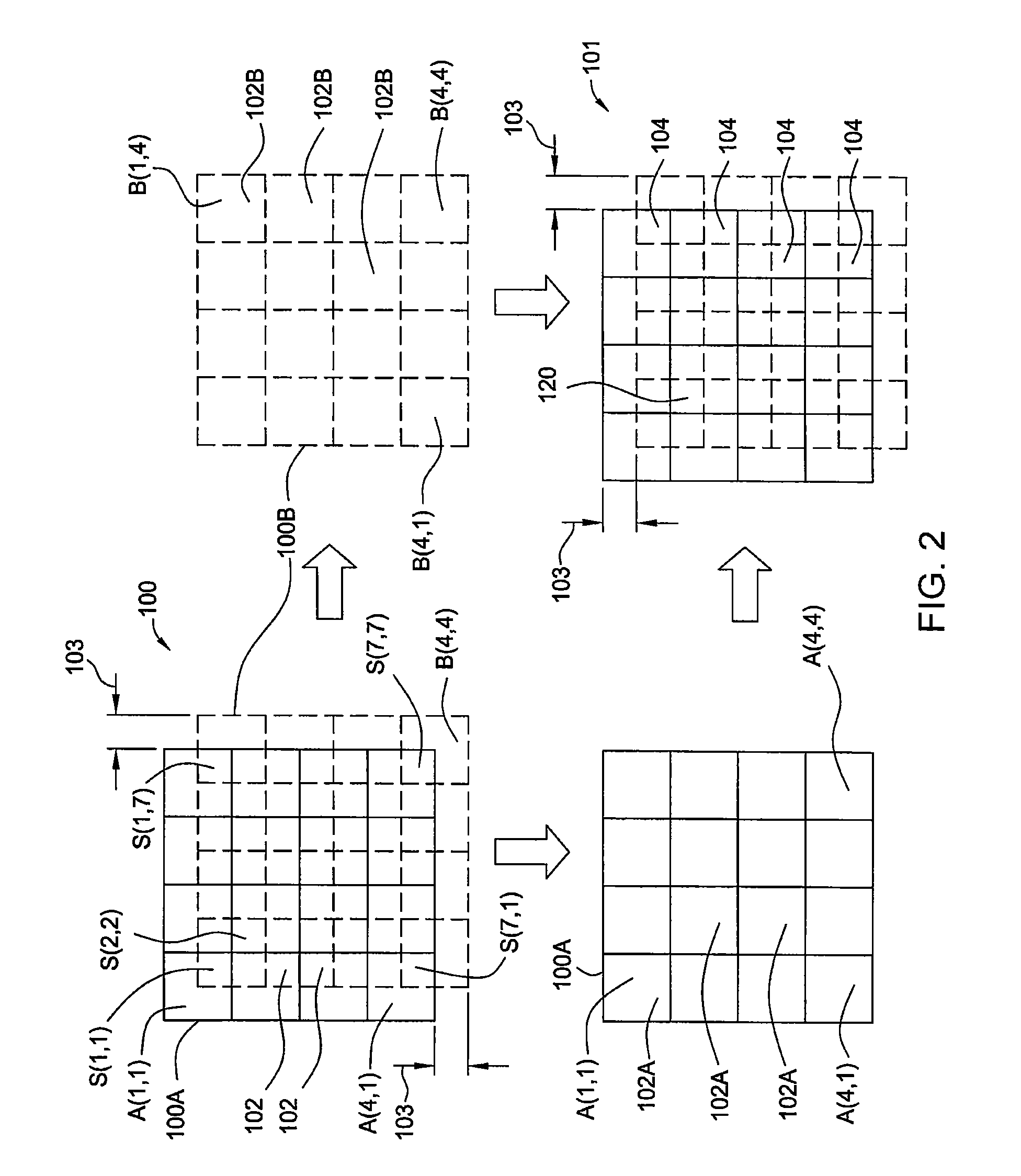
[0026] Embodiments of the invention contemplate methods and apparatus for providing a high-resolution image using multiple spatially offset lower-resolution spatial light modulators, such as DMD, LCOS, or HTPS. Multiple lower-resolution signals, or subframe signals, are generated from a high-resolution image signal using a resolution reduction and interpolation algorithm. The resolution reduction and interpolation algorithm defines each subframe signal from the high-resolution image signal so that the pixels of each subframe signal are spatially offset from the pixels of the other subframes a desired offset distance. In one embodiment, a digital overlay approach is used, in which the offset distance is equal to a fraction of the width of a single pixel. In another embodiment, an in-engine tiling approach is used, in which the offset distance is equal to a fraction of the width of the entire image so that the subframe images are positioned side-by-side.

[0027] In the overlay approach...


PUM


Abstract

A high-resolution image is generated using multiple spatially offset lower-resolution digital micro-mirror device (DMD) panels. Multiple lower-resolution subframe signals for controlling the spatial light modulators are generated from a high-resolution image signal using a resolution reduction and interpolation algorithm. The spatial light modulators under control of the subframe signals are illuminated by a light source and light beams reflected from the spatial light modulators are combined and directed onto a screen for display.

Description

CROSS-REFERENCE TO RELATED APPLICATIONS [0001] This application claims the benefit of U.S. Provisional Patent Application No. 60 / 851,105, entitled “Spatially Offset Multi-Panel Architecture for High Resolution Projection Displays,” filed on Oct. 11, 2006.BACKGROUND OF THE INVENTION [0002] 1. Field of the Invention [0003] Embodiments of the present invention relate generally to display systems, and, more particularly, to a system and method for projection display of an image. [0004] 2. Description of the Related Art [0005] Digital projection is used in televisions, projectors and video projectors. In digital projectors, a projected image is created by illuminating a spatial light modulator, such as a liquid-crystal-on-silicon (LCOS), a high-temperature polysilicon transmissive panel (HTPS) a deformable micro-mirror device (DMD), or other microelectromechanical system (MEMS) device. A deformable micro-mirror device is an array of small mirrors arranged in a typically rectangular matri...

Claims


Application Information

Patent Timeline
Patent Type & Authority Applications(United States)
IPC IPC(8): H04N5/72G03B21/14G03B21/28
CPCH04N9/3147G03B21/14G03B21/008G03B21/208
Inventor BELLIS, MATTHEW WILLIAMCHEN, DONGMINMILLER, GREGORY ALLEN
Owner MIRADIA INC
Learn More