
All-optical regenerator and optical network incorporating same

a technology of all-optical regenerators and optical networks, applied in electromagnetic transmission, electrical equipment, transmission, etc., can solve the problems of increasing complexity and sophistication of optical networks, affecting the operation of aors, so as to reduce size, cost, power consumption, and complexity. , to achieve the effect of reducing noise and distortion, reducing complexity and complexity

Active Publication Date: 2008-04-10
CIENA
View PDF20 Cites 55 Cited by
  • Summary
  • Abstract
  • Description
  • Claims
  • Application Information

AI Technical Summary

Benefits of technology

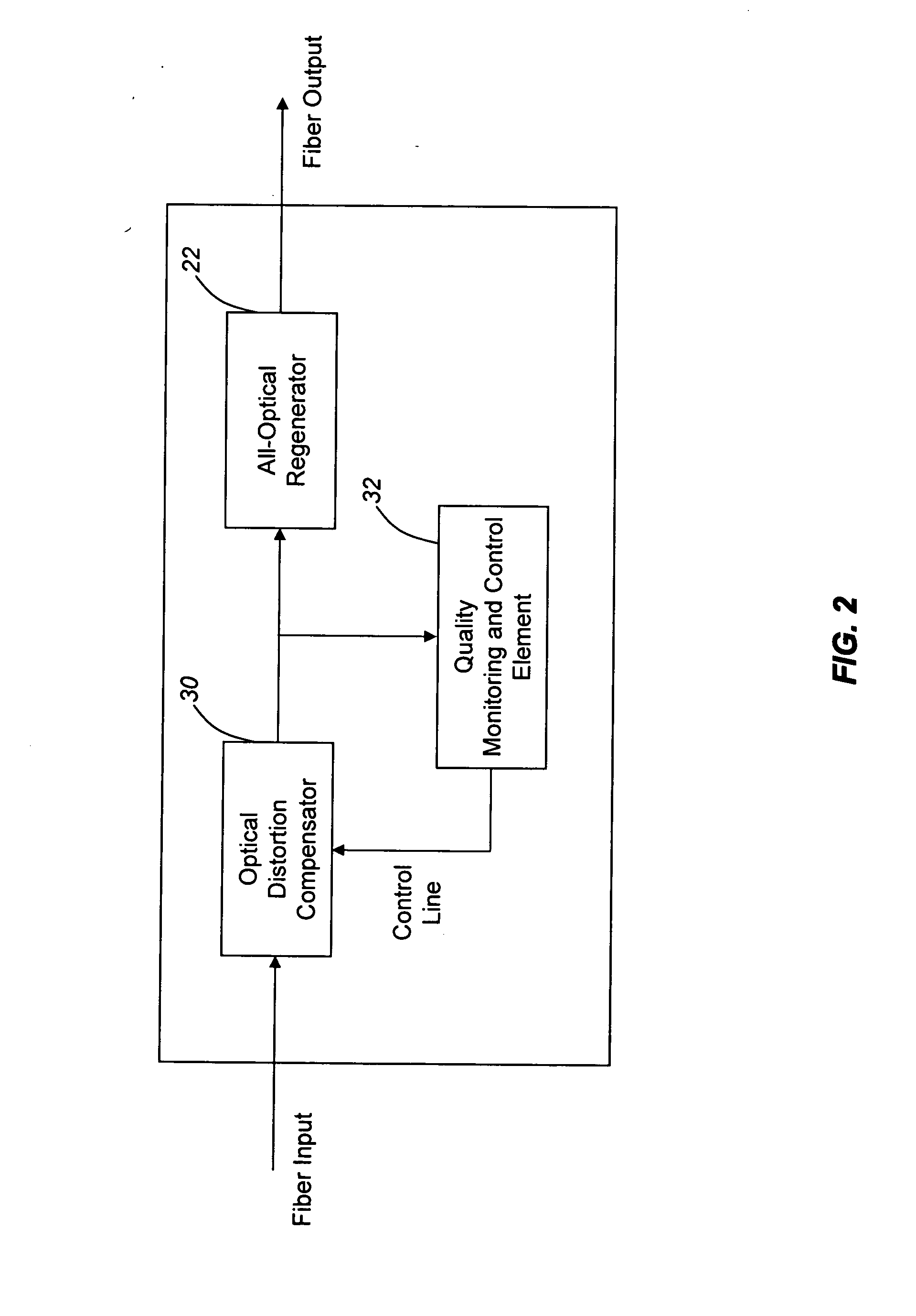
The present invention provides an all-optical regenerator that combines the functions of re-amplification, re-shaping, and re-timing with distortion compensation and performance monitoring of the optical signal. This configuration reduces the complexity and cost of the optical signal regeneration node relative to an OEO regeneration node, improves reliability, enhances application space, reduces overall complexity and cost of optical networks, provides full QoS capability for fault isolation and correction, and decouples the regeneration function from any specific optical signal protocol or framing structure. The all-optical regenerator device includes an all-optical regenerator, a distortion compensator, and a quality-of-signal monitoring device. The quality-of-signal monitoring device measures the optical signal after distortion compensation and provides feedback to the distortion compensator and other components of the optical network.

Problems solved by technology

As described above, optical networks continue to increase in sophistication and complexity.
Given the geographic reach of a typical optical network, and the associated environmental and measurement uncertainty, high-bit rate optical signals are often distorted to such an extent that an AOR may no longer be functional.
AORs typically do not inherently provide a performance monitoring functionality.

Method used


Image

  • All-optical regenerator and optical network incorporating same
  • All-optical regenerator and optical network incorporating same
  • All-optical regenerator and optical network incorporating same

Examples


Embodiment Construction

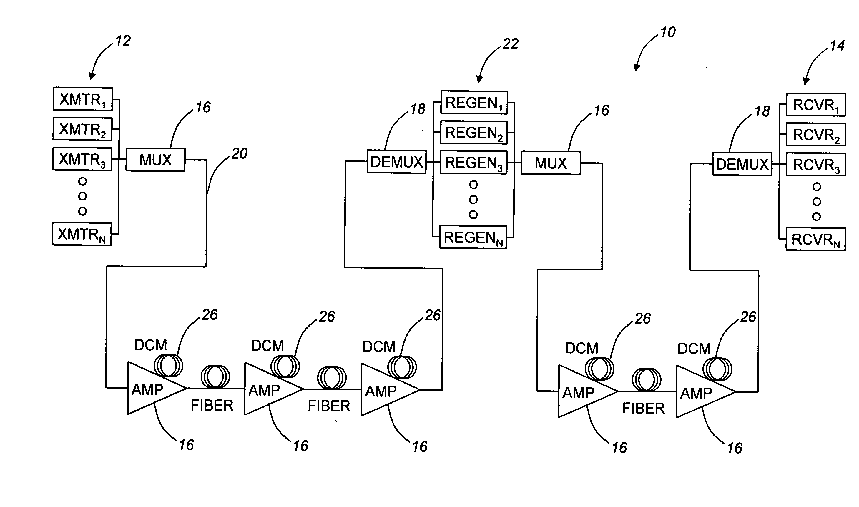
[0017]Typically, a regenerator node must eliminate signal noise and distortion through its re-amplify and re-shape (2R) functionality. Optionally, the regenerator node also provides a re-time (3R) functionality. Preferably, however, the regenerator node further provides a data or signal quality monitoring functionality for tunable distortion compensation, as well as a data or signal quality monitoring functionality for fault isolation and correction switching mechanisms.

[0018]All-optical regenerators may be based on several principles, as described below. For example, all-optical regenerators may be based on cross-gain modulation (XGM), cross-phase modulation (XPM), or four-wave-mixing (FWM) in semiconductor optical amplifiers. Alternatively, all-optical regenerators may be based on nonlinear effects in optical fibers. In general, all-optical regeneration is a process that removes the noise from optical signals and restores the optical signals to well-defined levels for further tran...


PUM


Abstract

The present invention provides an optical networking device for re-amplifying, re-shaping, and re-timing an optical signal, as well as providing distortion compensation and performance monitoring of the optical signal. The optical networking device includes an all-optical regenerator device for one or more of re-amplifying, re-shaping, and re-timing the optical signal; a distortion compensator device for compensating for distortion associated with the optical signal; and a quality-of-signal monitoring device for measuring the quality of the optical signal. Preferably, the all-optical regenerator device, the distortion compensator device, and the quality-of-signal monitoring device are disposed within a single module. The quality-of-signal monitoring device measures the optical signal subsequent to distortion compensation. Alternatively, the quality-of-signal monitoring device measures the optical signal subsequent to distortion compensation and all-optical regeneration. In various embodiments, the quality-of-signal monitoring device provides feedback to the distortion compensator device, a distortion compensator device disposed along a line system, one or more of an optical amplifier and a distortion compensator device disposed along the line system, and a transmitter device disposed along the line system.

Description

FIELD OF THE INVENTION[0001]The present invention relates generally to an all-optical regenerator (AOR) and an optical network incorporating the same. More specifically, the present invention relates to an AOR that re-amplifies and re-shapes an optical signal, and which incorporates a re-timing functionality, distortion compensation functionality, and a performance monitoring functionality.BACKGROUND OF THE INVENTION[0002]Over the course of the past decade, optical networks have evolved from simple single-channel synchronous optical network (SONET) regenerator-based links to multi-span, multi-channel optically amplified ultra-long-haul transport systems, necessitated by the high demand for increased bandwidth at a reduced cost. Typically, the cost of a well-designed high-capacity transport system is dominated by the number of optical-to-electrical (OE) and electrical-to-optical (EO) conversions that are required. As the reach and channel capacity of such transport systems continues ...

Claims


Application Information

Patent Timeline
Patent Type & Authority Applications(United States)
IPC IPC(8): H04B10/00
CPCH04B10/0795H04B10/299H04B10/25133
Inventor FRANKEL, MICHAEL Y.
Owner CIENA
Learn More