Layout configuration of flat display device

a display device and configuration technology, applied in static indicating devices, printed circuit non-printed electric components association, instruments, etc., can solve the problems of high cost, interference effect between power cord and adjacent electronic components, and inability to reduce complexity and cos

Inactive Publication Date: 2008-04-10
JEAN
View PDF4 Cites 29 Cited by
  • Summary
  • Abstract
  • Description
  • Claims
  • Application Information

AI Technical Summary

Benefits of technology

[0011] The present invention provides a layout configuration of a flat display device to reduce complexity and cost for mounting electronic components of the flat display device. In addition, the reduction of interference and the electric safety are also considered in the present invention.

Problems solved by technology

However, these separated four printed circuit boards PCB1, PCB2, PCB3 and PCB4 occupy much space, which is disadvantage for minimization of the overall LCD device.
Sometimes it strides across some electronic components of the printed circuit boards PCB2 and PCB3, and thus some interference effects may occur between the power cord and the adjacent electronic components.
Afterward, too many connectors take much space and are not cost-effective.

Method used


Image

  • Layout configuration of flat display device
  • Layout configuration of flat display device
  • Layout configuration of flat display device

Examples


Embodiment Construction

[0034] The present invention will now be described more specifically with reference to the following embodiments. It is to be noted that the following descriptions of preferred embodiments of this invention are presented herein for purpose of illustration and description only. It is not intended to be exhaustive or to be limited to the precise form disclosed.

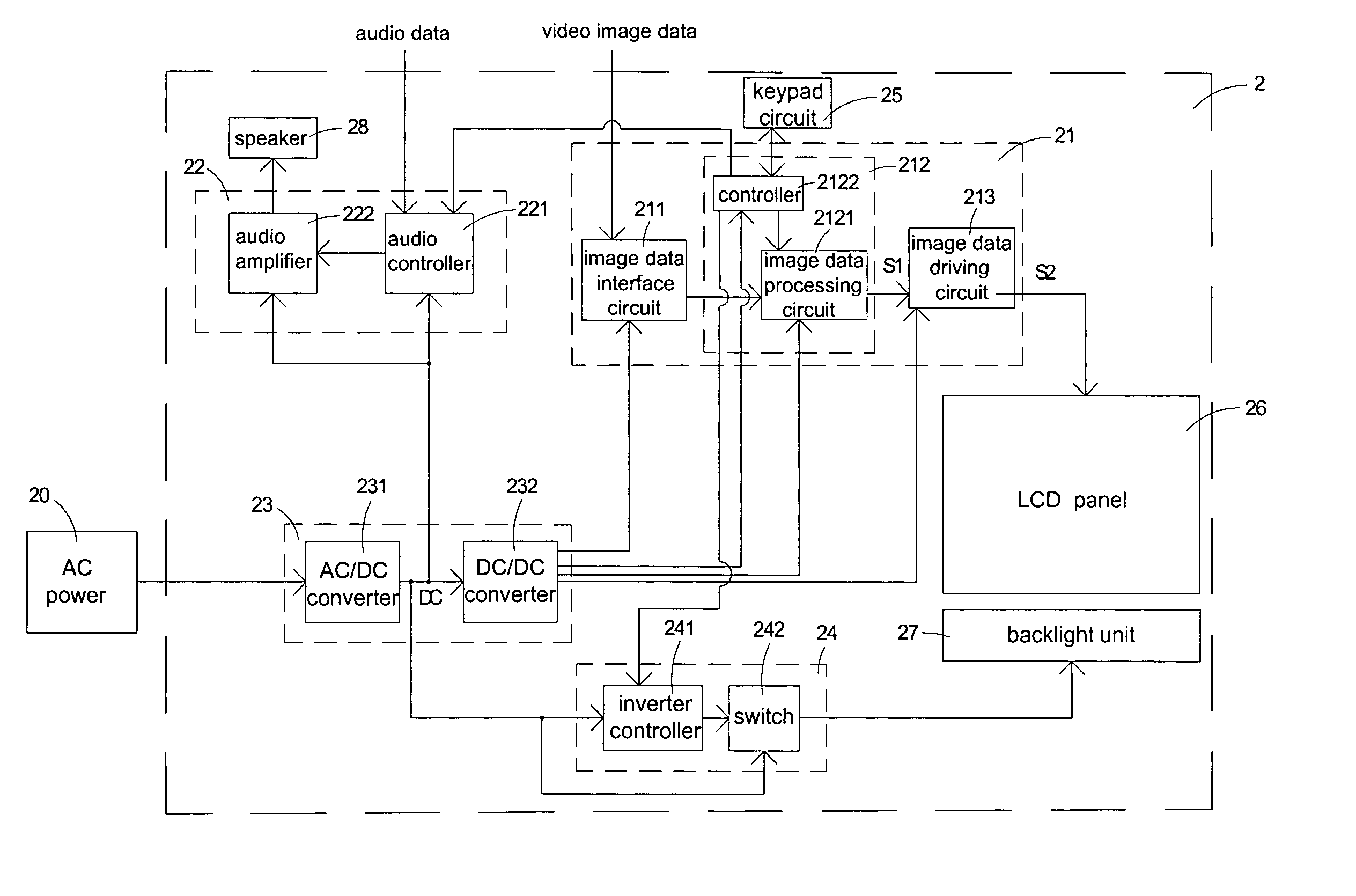
[0035] Referring to FIG. 3, a schematic circuit block diagram of the flat display device according to a first preferred embodiment of the present invention is illustrated. In this embodiment, the flat display device is a LCD device 2, but not limited thereto. The LCD device 2 comprises a video unit 21, an audio unit 22, a power unit 23, a backlight driving unit 24, a keypad circuit 25, a LCD panel 26, a backlight unit 27 and a speaker 28, wherein the audio unit 22 is optionally disposed in the LCD device 2. The power unit 23 of the LCD device 2 is connected to a commercial AC power 20 for providing power to the video unit 21, a...


PUM


Abstract

The present invention relates to a layout configuration of a flat display device. The flat display device receives an AC power and comprises a display panel and a backlight unit. The layout configuration of the flat displace device comprises a video unit, a backlight driving unit and a power unit mounted on a one-layer printed circuit board and electrically connected to each other via electrical traces of the one-layer printed circuit board. The video unit controls the display panel and has an image data interface circuit, an image data processing and controlling unit, and an image data driving circuit. The backlight driving unit drives the backlight unit for emitting light to the display panel. The power unit is connected to the AC power and has an AC/DC converter and a DC/DC converter for providing power to the video unit and the backlight driving unit.

Description

CROSS-REFERENCE TO RELATED APPLICATION [0001] This application is a continuation-in-part of U.S. patent application Ser. No. 11 / 067,693, filed on Mar. 1, 2005, and entitled “LAYOUT CONFIGURATION OF FLAT DISPLAY DEVICE”. The entire disclosures of the above applications are all incorporated herein by reference.BACKGROUND OF THE INVENTION [0002] The present invention relates to a layout configuration, and more particularly to a layout configuration of a flat display device. Recently, due to the advantages of thin profile, light weight, low driving voltage and low power consumption, various flat display devices are increasingly developed. The commonly used flat display devices include liquid crystal display (LCD) devices, electroluminescent display (ELD) devices, and vacuum fluorescent display (VFD) devices. [0003] Referring to FIG. 1, a schematic circuit block diagram of a typical LCD device is shown. The LCD device 1 comprises a LCD panel 11, an interface circuit 12, a control circuit...

Claims


Application Information

Patent Timeline
Patent Type & Authority Applications(United States)
IPC IPC(8): G09G3/10H05B37/00
CPCG02F1/13452H05K1/0256H05K1/18H05K2201/10128H05K2201/09972H05K2201/1003H05K2201/09063G09G3/3406G09G2330/02H05B45/30G09G3/10
Inventor TSAI, TUNG-YI
Owner JEAN
Why Eureka
Try Eureka