Armored plating system

a technology of armored plating and armor plate, which is applied in the direction of armor, protective equipment, weapons, etc., can solve the problems of uncompletely understanding the long-range health implications of human interaction with these particles, insufficient armored plating knowledge, and worse accidents, and achieves low weight, low cost, and high performance.

Inactive Publication Date: 2008-04-10
RAMPGATE LTD A TEXAS
View PDF6 Cites 5 Cited by
  • Summary
  • Abstract
  • Description
  • Claims
  • Application Information

AI Technical Summary

Benefits of technology

[0011]In satisfaction of the above, the present invention provides an improved armored plate system that offers high performance, low weight, and low cost. The present invention, by way of a novel use of components, and a novel combination of those components, provides for armor that can safely stop incoming bullets that known systems cannot. Also, the present invention avoids the hazards associated with known armor in so much as it is not friable. Nevertheless, the present system remains as flexible and as lightweight as known armored plate systems.
[0012]The present system is characterized by a series of tubes arranged with one another to form a protective array. Each tube slides past adjacent tubes to fit into place. These tubes have slanted sidewalls so that one overlaps the next to provide continuous protection even when the array is placed on a curved surface. Within each tube, a series of laminated and embossed components are layered upon one another. These laminated pieces act in concert to absorb and dissipate kinetic energy of a bullet striking the apparatus. Energy associated with an incident bullet is distributed along and between each laminated piece. The embossed pieces serve to hold laminated members in alignment and allow each tube to bend while preserving the integrity of each laminated member.
[0013]Particular forms of the system are thought to have laminated components of one or more particular finishes. For instance, useful forms are envisioned where laminated components have a powder coat finish or carbide finish. Other forms of the present invention are thought to be particularly useful where the component pieces of the armor system are strengthened with basalt. Such a form is thought to be particularly advantageous as basalt provides for extraordinary high strength yet is lightweight.
[0014]In view of the above, the present system solves problems associated with known protective armor. The present apparatus does not rely on friable material that often irritates the skin, eyes, and lungs. Reducing the friction associated with an incoming bullet, such as with a TEFLON coating, will not thwart the effectiveness of the present invention. The combination of system components lends itself to flexibility in fitting around curved surfaces while offering seamless protection. Finally, the present system may have protective finishes that further strengthen the system.

Problems solved by technology

In some instances, these casualties are made worse by troops not wearing protective armor; or, because the armor the troops were wearing could not stop the incoming bullet or shrapnel.
Further, the long-range health implications associated with human interaction with these particles are not completely understood.
Known armored plating is inadequate for other reasons as well.
Currently known armor cannot safely stop these types of bullets.
A back-and-forth struggle exists between updating the armor worn for protection and the weapons used to penetrate that protection
Armor considered acceptable for use with military and law enforcement personnel, in light of recent changes in minimum acceptable standards, will soon be considered insufficient.
Currently known armor worn by military and law enforcement personnel cannot stop an “armor piercing” bullet.
Moreover, such known products have proven unsatisfactory in safely stopping the very type of object produced by explosive devices currently used by insurgents in Iraq.

Method used


Image

  • Armored plating system
  • Armored plating system
  • Armored plating system

Examples


Embodiment Construction

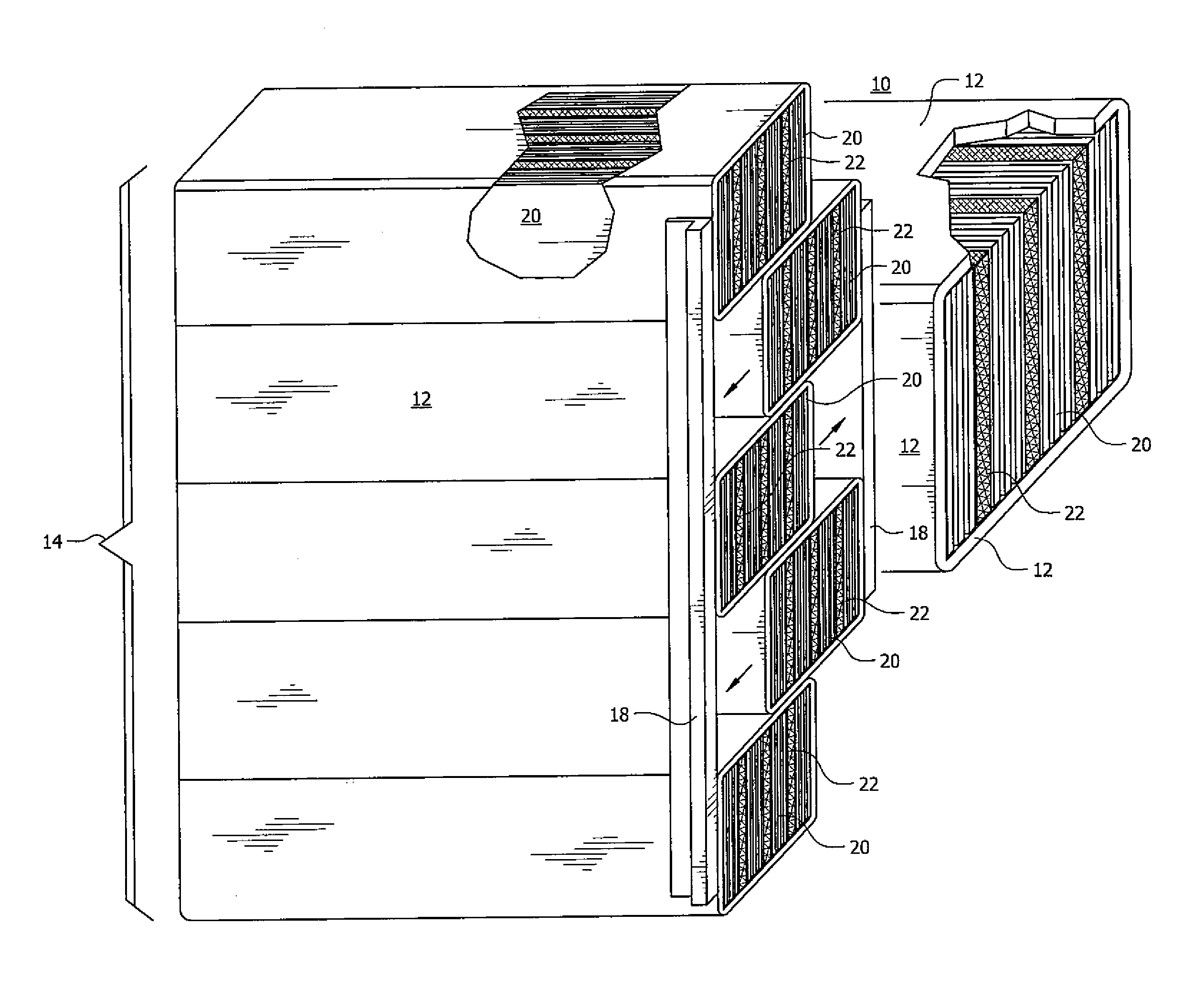
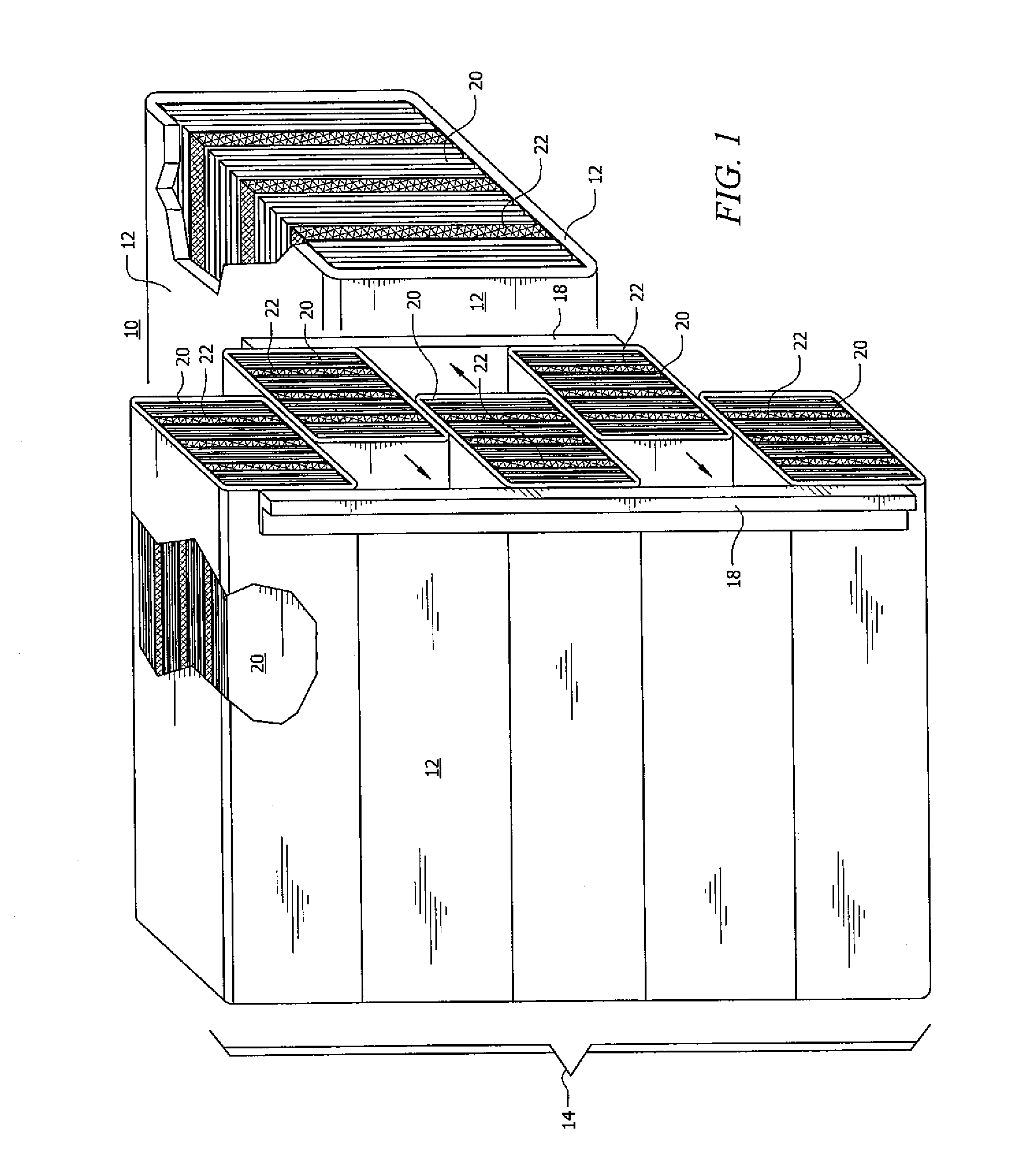
[0027]Referring to FIG. 1, the apparatus of the present invention is generally designated by the reference numeral 10. The most useful embodiments of apparatus 10 are envisioned as being used to fit both military and law enforcement personnel and the vehicles that transport those personnel. As will be discussed in greater detail, apparatus 10 lends itself to efficient storage and transport, making it ideal for being shipped to troops all over the world.

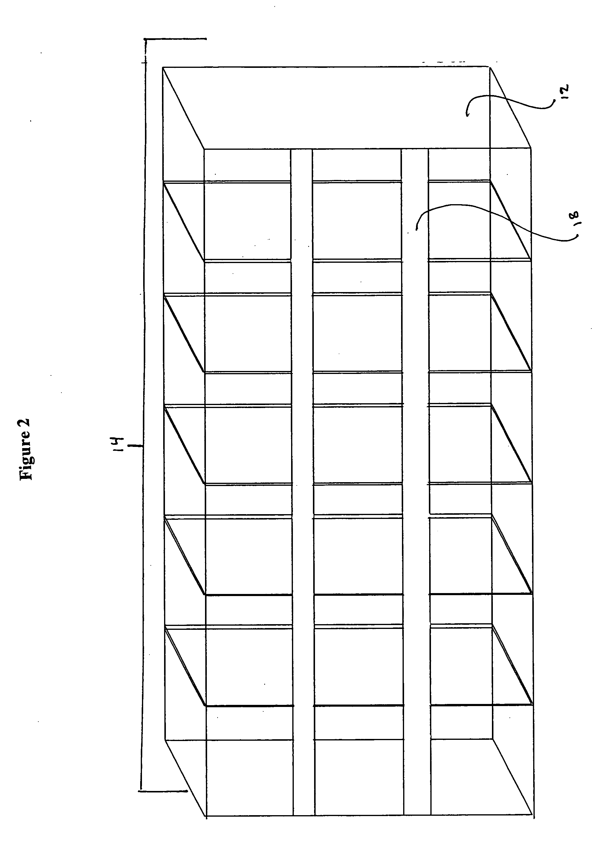
[0028]Apparatus 10 is characterized by a series of housing tubes 12. In the preferred embodiment, housing tubes 12 are elongate tube members having a rectilinear cross section. Each housing tube 12 is arranged with one another in parallel fashion along its length. The assembly of each housing tube 12 forms a protective array 14. As best seen in FIG. 1 and FIG. 2, each housing tube 12 has slanted sidewalls so that, when arranged, an intermediate tube sufficiently overlaps the next tube and is sufficiently overlapped by the previous tub...


PUM


Abstract

An improved armored plating system having a series of elongate tubes arranged in parallel fashion to form a protective array. Each tube has a rectilinear cross section with slanted sidewalls so that each tube partially overlaps the following tube and is partially overlapped by the previous tube. As such, the protective array may be placed on a curved surface while having no gaps in protection. The protective array is formed as alternating tubes slide past one another from opposing directions. A series of laminated members and an embossed member are slideably inserted into each tube and layered upon one another.

Description

BACKGROUND OF THE INVENTION[0001]1. Field of the Invention[0002]The present invention generally relates to an armored plating system. More specifically, the present invention relates to an improved armored plating system having laminated pieces and an embossed piece layered upon one another and where these pieces are contained in a series of array-forming tubes.[0003]2. Background Information[0004]The importance of armored plating seems obvious, yet cannot be overstated. One could reasonably argue that the importance of having reliable armored plating is more important than it ever has been. Such an argument could be made in view of several recent changes around the world. Currently, United States troops are placed under enemy fire on a daily basis on foreign soil. It is common to see daily casualty reports streaming in from the likes of Iraq and Afghanistan. In some instances, these casualties are made worse by troops not wearing protective armor; or, because the armor the troops w...

Claims


Application Information

Patent Timeline
Patent Type & Authority Applications(United States)
IPC IPC(8): F41H5/02
CPCF41H5/0414F41H5/045F41H5/0442F41H5/0421
Inventor JONES, DANCLARK, DEVANE
Owner RAMPGATE LTD A TEXAS
Why Eureka
Try Eureka