
Fiber optic tissue ablation

Inactive Publication Date: 2008-04-03
OPTECH VENTURES
View PDF14 Cites 60 Cited by
  • Summary
  • Abstract
  • Description
  • Claims
  • Application Information

AI Technical Summary

Benefits of technology

[0009]It is an object of the present invention to provide improved apparatus and methods for using laser quickly and efficiently to create elongated, lesions of precisely controlled depth and severity in vivo.
[0021]In an exemplary embodiment, the side emitting diffuser terminates distally into a structure selected from the group including a corner cube retro-reflector, a right angle prism, and a multilayer dielectric mirror, among other structures that can provide retro-reflectivity.
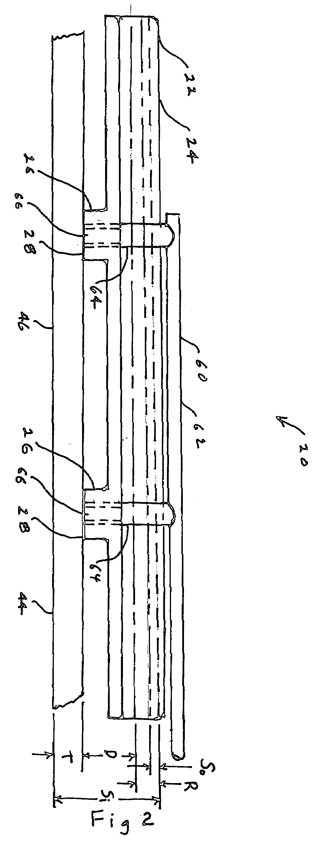
[0033]The spacing of the reflector and the side emitting fiber provide a convergent beam, and the spacing of the tissue contacting surfaces allow the beam to converge so that it is no closer than the distal wall of the tissue that is under treatment. This beam shape and placement will allow the energy density to remain high as the beam traverses the tissue, while possibly not exactly equal through the tissue thickness, at least compensating by greater concentration for the decrease in energy.

Problems solved by technology

Because the maze procedure is complex and prolonged and entails cardiopulmonary bypass, interventionists have pursued alternative means of creating lesions, most commonly by delivering radio frequency energy to the heart tissue through a catheter.
Unfortunately, these procedures can damage the heart.
However, end-emitting laser technologies have not met the needs of interventionists performing partial maze procedures.
Because tissue absorbs and scatters the laser radiation, an attempt to deliver sufficiently intense radiation to assure a lesion at a depth of 4 millimeters may have the undesired effect of delivering overly intense radiation at a lesser depth, charring or vaporizing the intervening tissue and creating coagulum which may adhere to the emitting apparatus and interfere with its operation.

Method used


Image

  • Fiber optic tissue ablation
  • Fiber optic tissue ablation
  • Fiber optic tissue ablation

Examples


Embodiment Construction

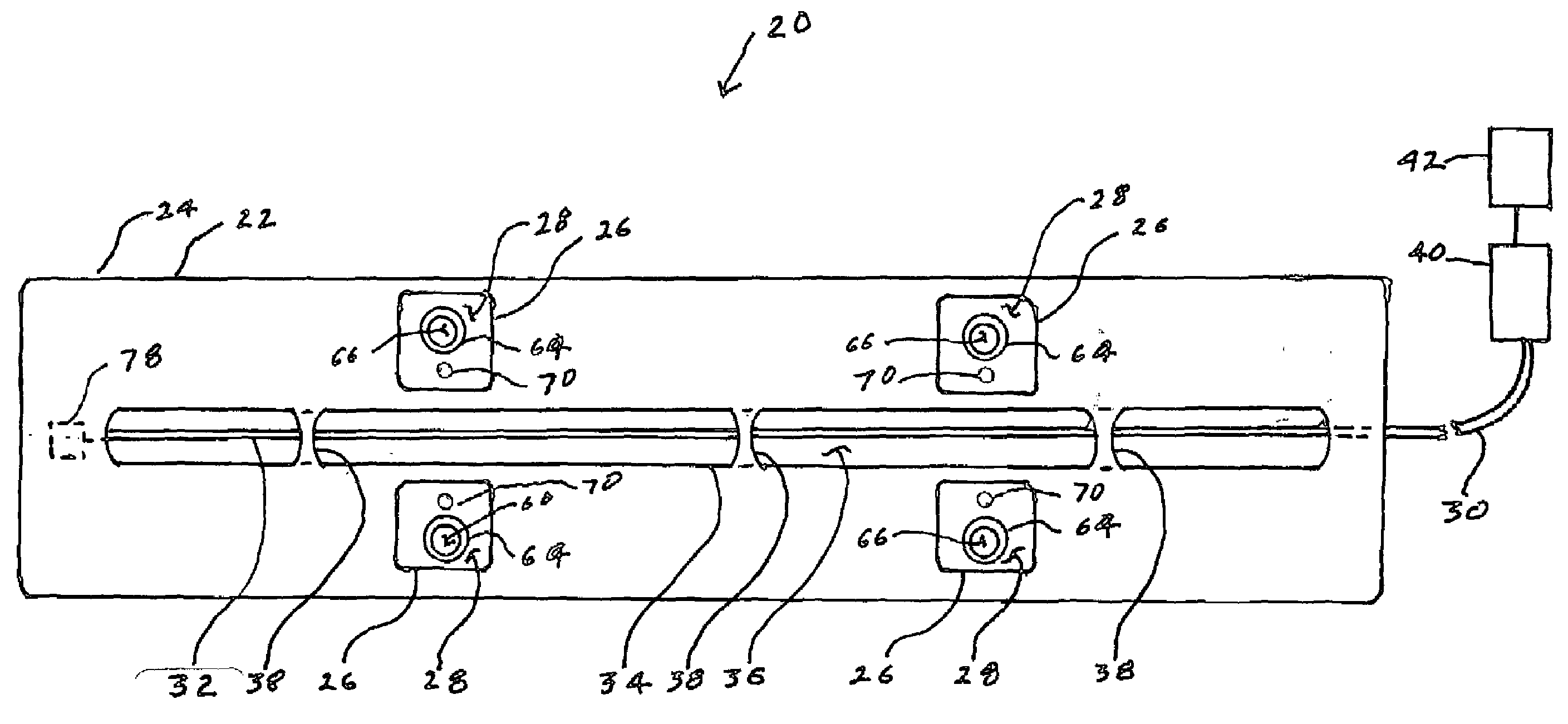
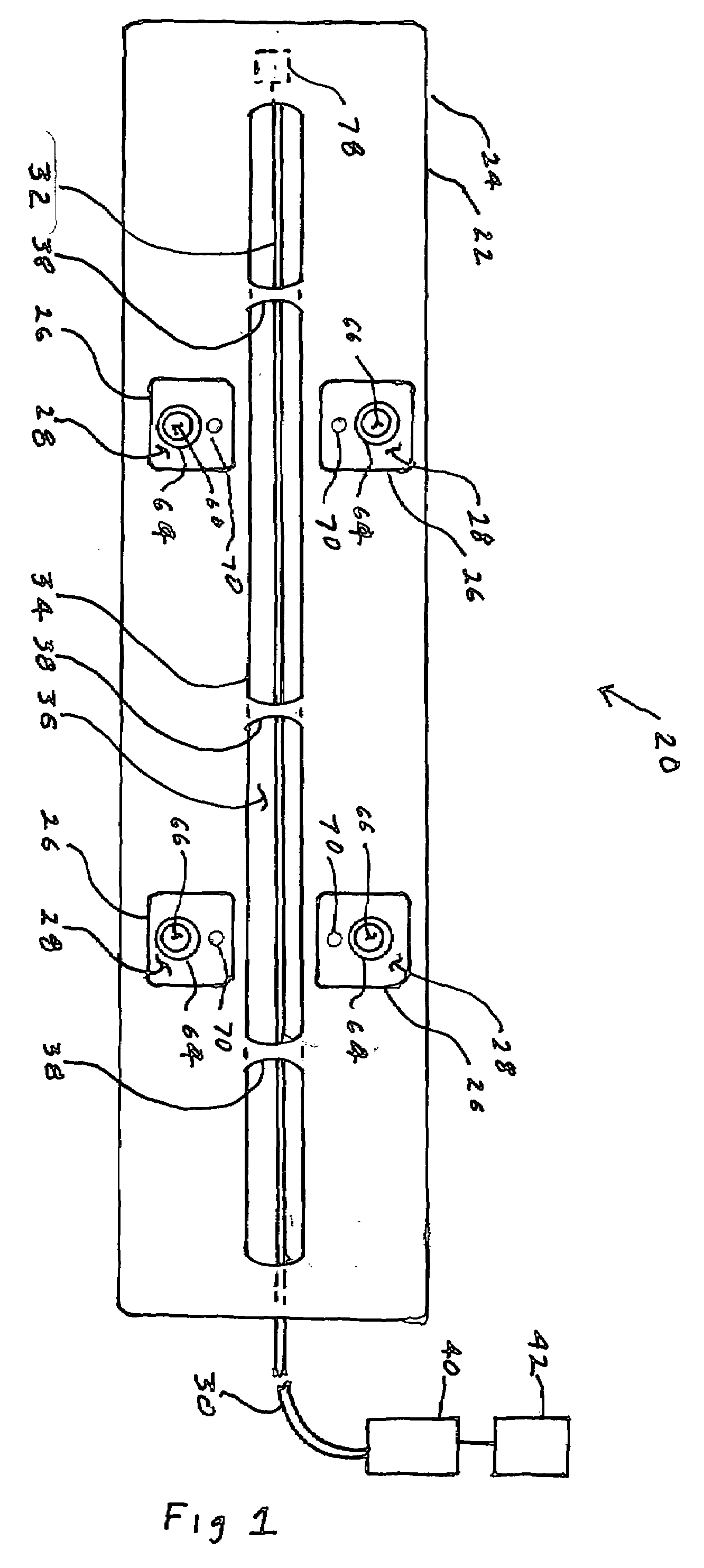
[0044]The present invention is an energy delivery system and method for performing laser ablation procedures using side emitting optical fibers emitting energy from a laser source to tissue to be treated. The system employs a catheter that includes a side emitting long period grating diffuser, in an exemplary version in the range of for example 5-10 cm, imprinted on the distal end of an optical fiber waveguide to make continuous photocoagulation lesions for effective treatments. The side emitting fiber optic high energy delivery platform uniformly emits optical energy over the length of the diffuser. The diffuser is housed in a flexible extended optical reflector channel to increase the energy delivery efficiency of the laser source. A distributed temperature sensor array, for monitoring the in-depth temperature gradient in the tissue during the procedure, is embedded in the diffuser housing, and extends along the length of the tissue under treatment. A series of openings connected ...


PUM


Abstract

A catheter tip for delivering laser light energy to create lesions extending to a depth of several millimeters in tissue includes an elongated, flexible housing. A reflector is oriented longitudinally in a channel the housing. A side emitting optical fiber diffuser, extending the length of the reflector, is held at a fixed separation from the reflector. The reflector and the side emitting diffuser are configured and spaced to provide a convergent beam directed through the tissue under treatment. Reflector curvature may be circular or elliptical in cross section, or other selected shape. The diffuser and reflector relative positioning being selected to place the beam focal point (or image) at a predetermined lateral distance from the reflector preferably not closer than the far wall of the tissue under treatment. Temperature probes are provided to monitor the temperature gradient through the tissue thickness. Optionally cooling and / or irrigation fluid are provided. Optionally, the fiber terminates at a retro-reflector.

Description

GOVERNMENT LICENSE RIGHTS[0001]This invention was made with Government support under grant number IR43HL079734-01 from the National Institutes of Health. The Government has certain rights in the invention.BACKGROUND[0002]1. Field of the Invention[0003]The present invention relates to medical interventional applications of fiber optics and especially to delivery of intense infrared for heating tissues.[0004]2. General Background and State of the Art[0005]The condition known as atrial fibrillation (AF) is characterized by rapid and irregular activation of the atria which leads to the loss of normal sinus rhythm, and contributes significantly to cardiovascular morbidity and mortality. The preferred surgical treatment of AF, known as a “maze procedure,” involves cutting the heart tissue to produce a pattern of lesions which tend to block the propagation of the irregular electrical activity that maintains the fibrillation. Because the maze procedure is complex and prolonged and entails c...

Claims


Application Information

Patent Timeline
IPC IPC(8): A61B18/18
CPCA61B18/24A61B2018/2272A61B2018/2261A61B2017/00084
Inventor RUBTSOV, VLADIMIRLAKA, HILLELLEVIN, MICHAELAKBARIAN, MINOOPESHKO, IGOR
Owner OPTECH VENTURES
Learn More