
Radiation image capturing apparatus and grid moving device

a technology of radiation image and moving device, which is applied in the field of radiation image capture apparatus, can solve the problems of affecting blurred images generated from radiation image information acquired, and limitations of efforts to increase the accuracy of grid movement control, so as to reduce grid irregularities and reduce load.

Inactive Publication Date: 2008-04-03
FUJIFILM CORP
View PDF14 Cites 12 Cited by
  • Summary
  • Abstract
  • Description
  • Claims
  • Application Information

AI Technical Summary

Benefits of technology

The present invention provides a radiation image capturing apparatus with a grid moving device that reduces grid irregularities and loads when the grid moves backward. The grid moving device moves the grid so that the speed at which it is moved is constant, and the time elapsed from the start of movement is minimized. This results in a reduction of radiation dose and improved image quality. The invention also includes a method for determining the coefficients of the equation used to describe the movement of the grid based on the minimum and maximum exposure times, as well as a control means for controlling the motor. The invention also provides a grid moving device that removes scattered radiation rays and reduces the time-dependent change in radiation dose.

Problems solved by technology

Consequently, an image generated from the acquired radiation image information tends to be blurred.
The disclosed grid moving mechanism requires that a complex control process be performed, which is liable to be affected by the AEC sensor.
Another problem is that if the exposure time is long, limitations are posed on efforts to increase the accuracy of the grid movement control.
The grid moving mechanism also is problematic in that the grid moving mechanism is subject to large loads, because the grid moves back at a high speed when it reaches the stroke end point.

Method used


Image

  • Radiation image capturing apparatus and grid moving device
  • Radiation image capturing apparatus and grid moving device
  • Radiation image capturing apparatus and grid moving device

Examples


Embodiment Construction

[0043]A radiation image capturing apparatus and a grid moving device according to an embodiment of the present invention, which are incorporated in a mammographic system, shall be described below with reference to FIGS. 1 through 14.

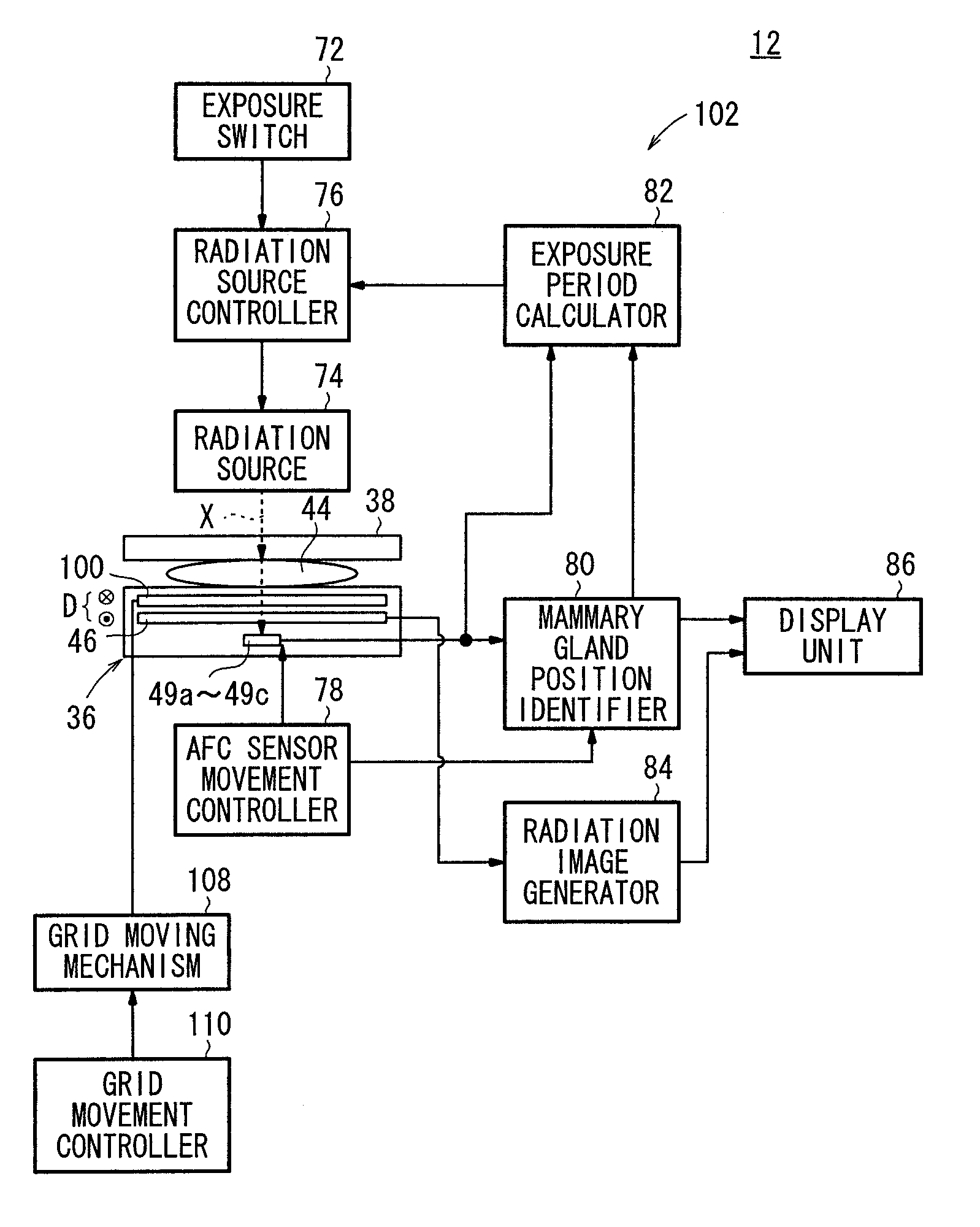
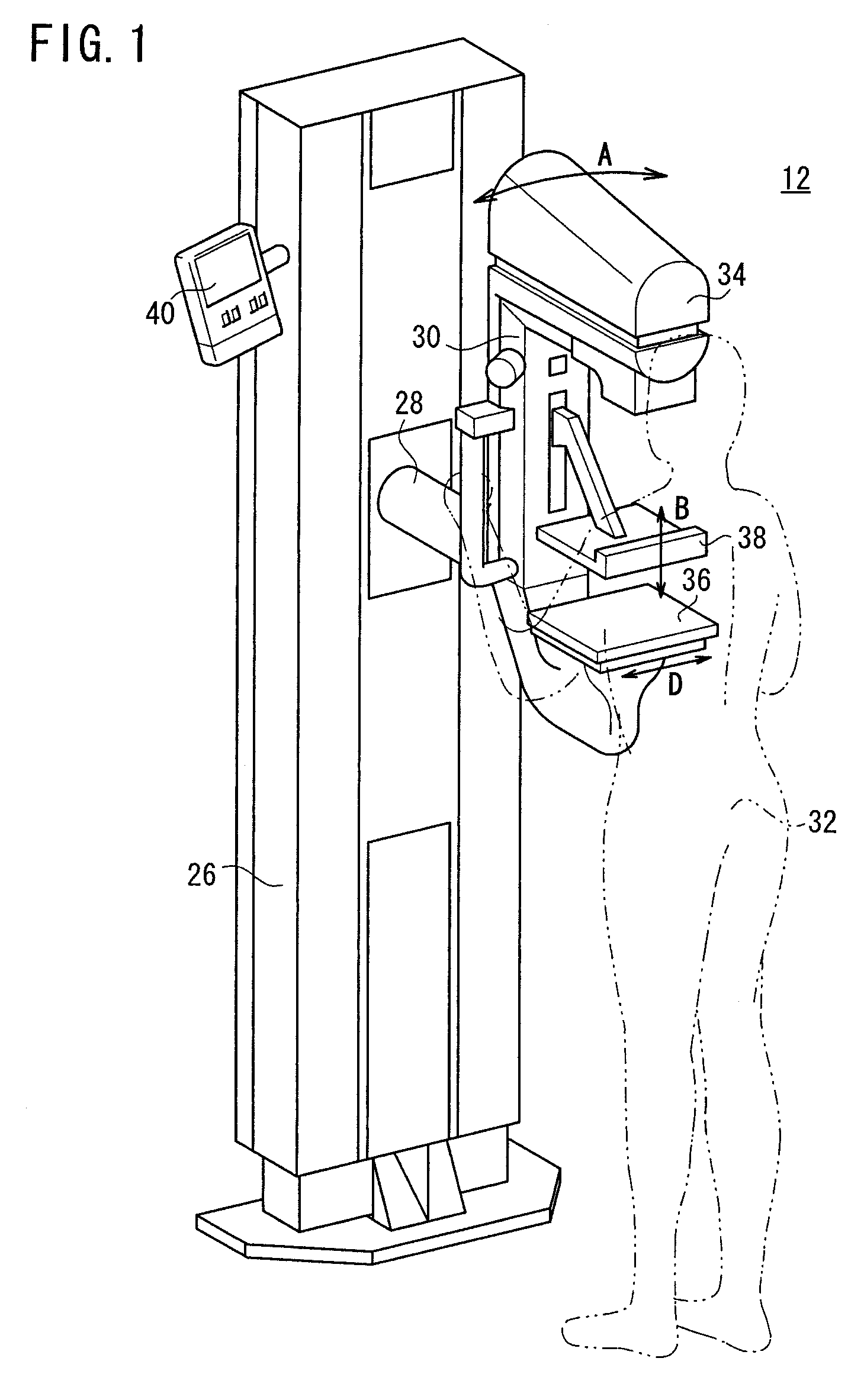
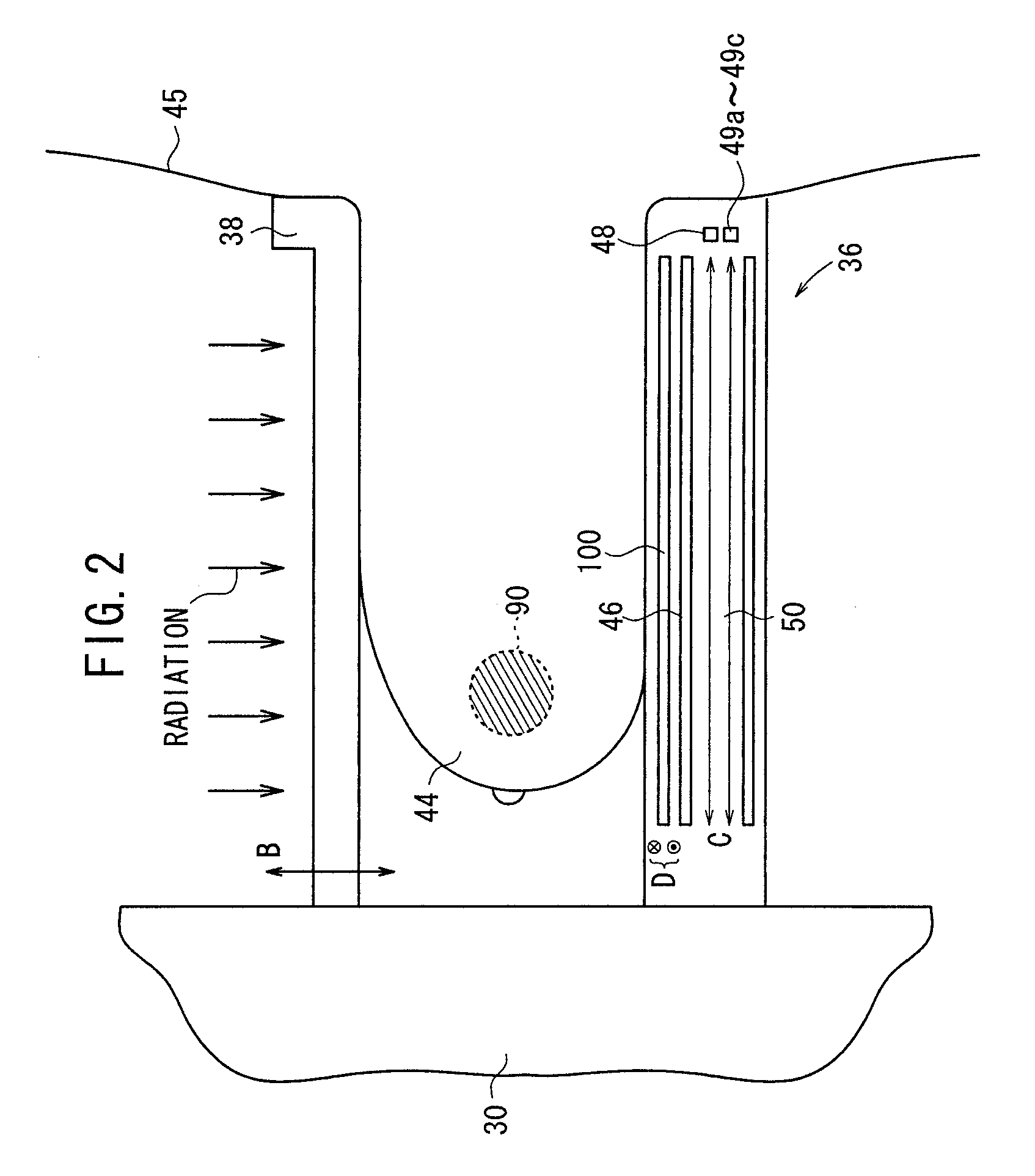
[0044]As shown in FIG. 1, a radiation image capturing apparatus 12 includes an upstanding base 26, a vertical arm 30 fixed to a horizontal swing shaft 28 disposed substantially centrally on the base 26, a radiation source housing unit 34 fixed to an upper end of the arm 30 and housing a radiation source for applying radiation to a breast 44 (see FIG. 2) to be imaged of a subject 32, an image capturing base 36 fixed to a lower end of the arm 30 and housing a solid-state detector 46 (radiation image information detector, see FIG. 2) for detecting radiation that has passed through the breast 44 in order to acquire radiation image information of the breast 44, and a breast compression plate 38 for pressing and holding the breast 44 against the image capturin...


PUM


Abstract

A radiation image capturing apparatus includes a radiation source for applying radiation to a subject, a radiation image information detector for detecting radiation from the radiation source that has passed through the subject in order to capture radiation image information of the subject, a grid disposed between the subject and the radiation image information detector for removing scattered radiation rays produced when the radiation passes through the subject, a grid moving mechanism for moving the grid in at least one direction, and a grid movement controller for controlling the grid moving mechanism. The grid moving mechanism moves the grid such that vt=constant, where v represents a speed at which the grid is moved and t represents a period elapsed from a time when the grid starts to move.

Description

BACKGROUND OF THE INVENTION[0001]1. Field of the Invention[0002]The present invention relates to a radiation image capturing apparatus, including a grid disposed between a subject to be imaged and a radiation image information detector for removing scattered radiation rays that are generated when radiation passes through the subject, together with a grid moving device for moving the grid.[0003]2. Description of the Related Art[0004]In the medical field, radiation image capturing apparatuses have widely been used, which apply radiation emitted from a radiation source toward a subject, and which guide the radiation that has passed through the subject to a solid-state detector or a stimulable phosphor panel in order to record radiation image information of the subject.[0005]The solid-state detector includes a solid-state detecting unit comprising a laminated assembly made up of a matrix of charge collecting electrodes formed on an insulating substrate, and a radiation conductor dispose...

Claims


Application Information

Patent Timeline
Patent Type & Authority Applications(United States)
IPC IPC(8): G21K1/02
CPCA61B6/502A61B6/4291G21K1/025A61B6/0414
Inventor YAMAKITA, HIROSHI
Owner FUJIFILM CORP
Learn More