
Method and apparatus for clock skew calibration in a clock and data recovery system using multiphase sampling

a clock and data recovery system technology, applied in the field of clock and data recovery techniques, can solve the problems of large percentage of design output variability mismatch, change of latch buffer delay, and uneven phase distribution of multi-phase clocks

Inactive Publication Date: 2008-04-03
AVAGO TECH INT SALES PTE LTD
View PDF5 Cites 39 Cited by
  • Summary
  • Abstract
  • Description
  • Claims
  • Application Information

AI Technical Summary

Benefits of technology

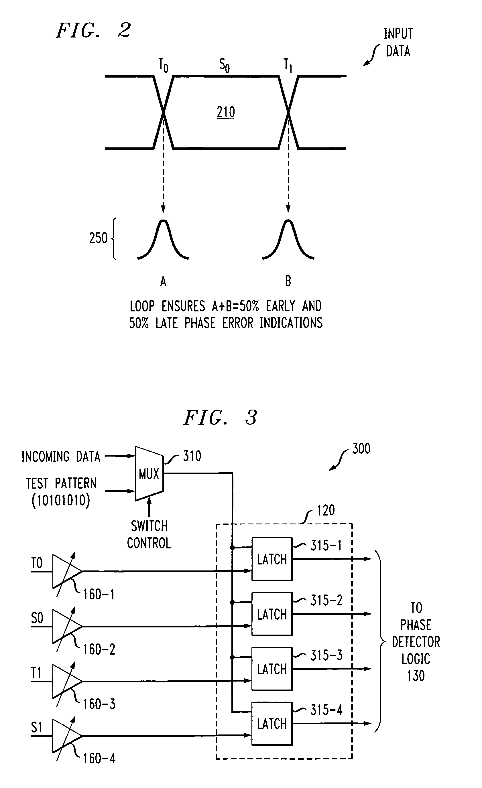
[0008]In an exemplary two UI sampling system, a phase of a first clock is adjusted and the clock and data recovery system automatically adjusts a phase of a second clock to ensure that the early-to-late ratio for the sum of both clocks is approximately 50%. The sample clocks can also be phase aligned with the transition clocks by (i) digitally re-mapping latch outputs in the bang-bang phase de...

Problems solved by technology

When the voltage controlled delay loops are implemented using integrated circuit technology, an inherent mismatch exists between the various delay stages, causing uneven phase distribution of the multi-phase clock in the generated phases of the clock sources.
It has been found that even a small processing mismatch can cause a large percentage mismatch in design output variability.
While the disclosed trimming process effectively compensates for mismatched latch buffers, the disclosed techniques may change the delay of the latch buffer, because the reference signal for calibration will not have the same amplitude and slew rate as the signal used in steady-state data recovery.
In addition, resistance-capacitance (RC) delays associated with the routing of the reference signal may affect the arrival of the clock edges at the clock buffers.

Method used


Image

  • Method and apparatus for clock skew calibration in a clock and data recovery system using multiphase sampling
  • Method and apparatus for clock skew calibration in a clock and data recovery system using multiphase sampling
  • Method and apparatus for clock skew calibration in a clock and data recovery system using multiphase sampling

Examples


Embodiment Construction

[0018]The present invention provides method and apparatus for clock skew calibration in a clock and data recovery system. Generally, the present invention uses the clock and data recovery system running in a closed loop and steady state mode, to calibrate the clock buffer skew by choosing a specific data pattern to which the clock and data recovery system is locked, and by selectively altering the behavior of the phase detector in order to calibrate specific clock buffers relative to a single clock buffer. The minimal calibration circuitry required does not introduce additional impairments into the measurement, and thus degrade the quality of the measurement and correction of the clock buffer skew.

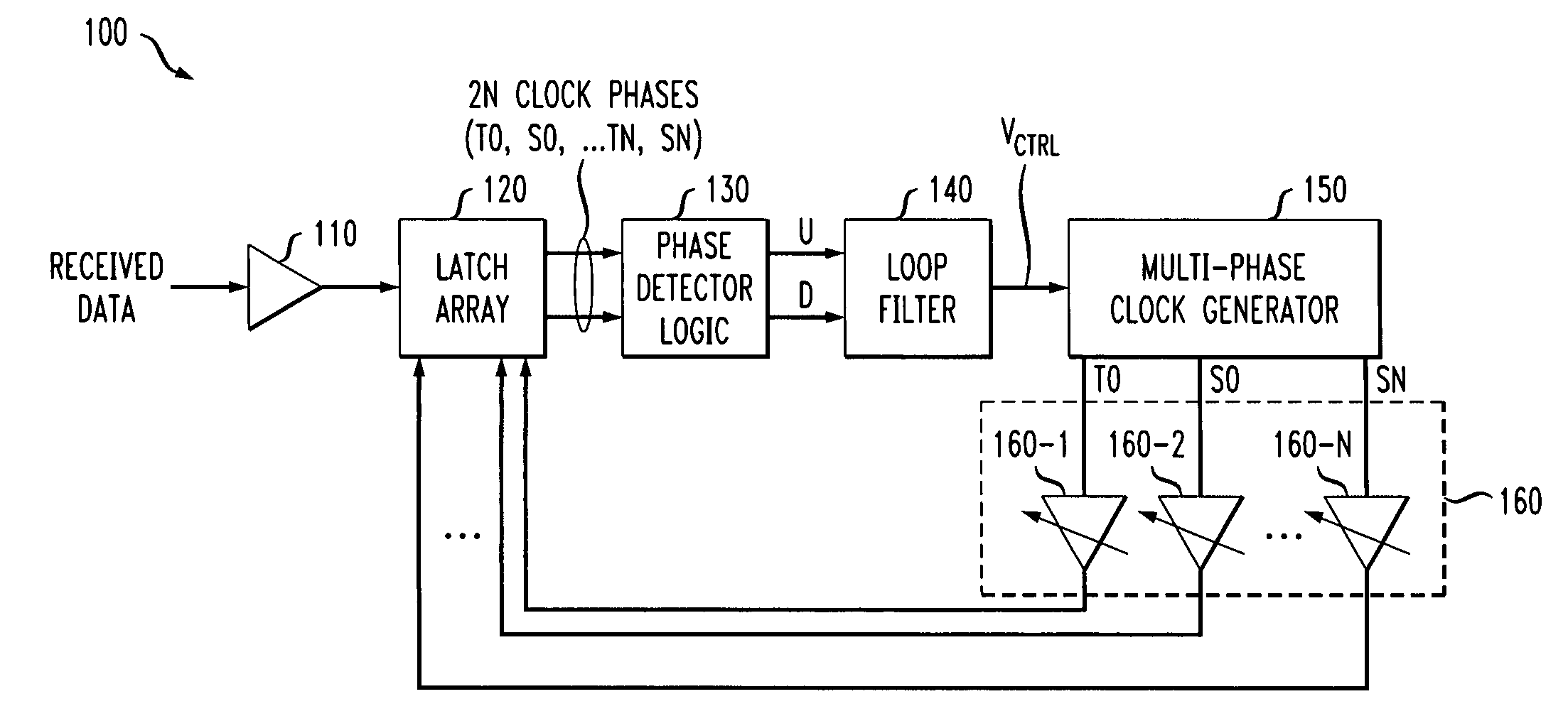
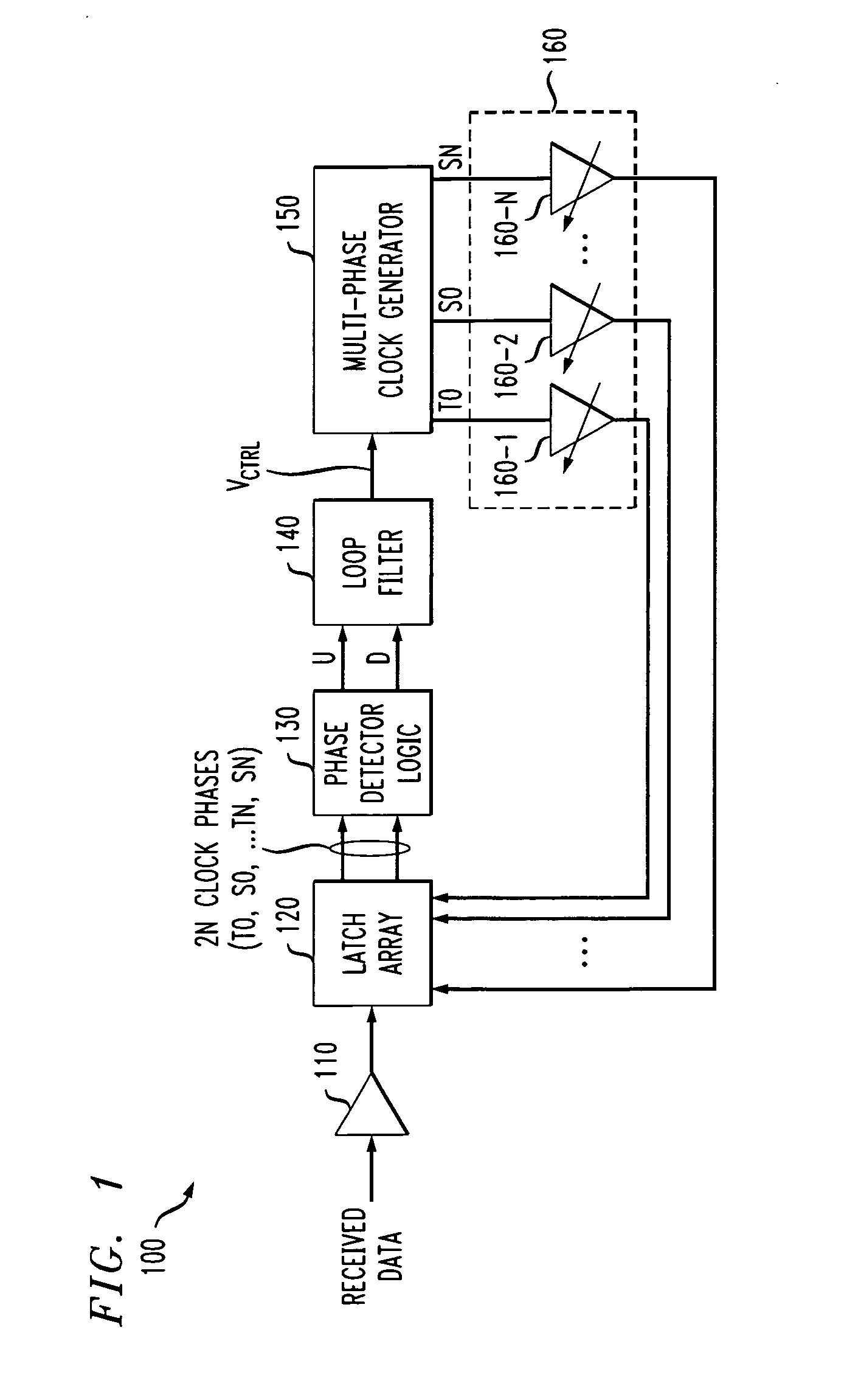
[0019]FIG. 1 illustrates an exemplary clock and data recovery system 100 in which the present invention can operate. As shown in FIG. 1, the exemplary clock and data recovery system 100 comprises an analog front end (AFE) 110, a latch array 120, phase detector logic 130, a loop filter 140,...


PUM


Abstract

Methods and apparatus are provided for clock skew calibration in a clock and data recovery system. One aspect of the invention compensates for skew among a plurality of clocks in a clock and data recovery system. The clocks are applied to a plurality of latches to sample an incoming signal. A reference signal, such as a Nyquist signal, is applied to a data input of each of the latches. Statistics of “early” and “late” corrections applied to at least one of the clocks by a bang-bang phase detector in the clock and data recovery system are evaluated and a delay of a clock buffer associated with the at least one clock is adjusted to obtain approximately a 50% early-to-late ratio for the at least one clock. The clock and data recovery system ensures that the early-to-late ratio for the sum of the plurality of clocks is approximately 50%.

Description

FIELD OF THE INVENTION[0001]The present invention is related to techniques for clock and data recovery (CDR) and, more particularly, to methods and apparatus for generating and aligning different phases of a clock signal.BACKGROUND OF THE INVENTION[0002]In many applications, including digital communications, clock and data recovery (CDR) must be performed before data can be decoded. Generally, in a digital clock recovery system, a reference clock signal of a given frequency is generated together with a number of different clock signals having the same frequency but with different phases (also known as a multi-phase clock). In one typical implementation, the different clock signals are generated by applying the reference clock signal to a delay network. Thereafter, one or more of the clock signals are compared to the phase and frequency of an incoming data stream and one or more of the clock signals are selected for data recovery.[0003]A number of existing digital CDR circuits use vo...

Claims


Application Information

Patent Timeline
IPC IPC(8): H04L7/00H03D3/24
CPCH03L7/0812H03L7/091H04L7/10H04L7/033H04L7/046H03L7/0992
Inventor GIBBONS, TOMPAIST, KENNETH W.TRAFFORD, MARKWILSON, WILLIAM B.
Owner AVAGO TECH INT SALES PTE LTD
Learn More