
Method and apparatus for user equipment registration

a user equipment and registration technology, applied in the field of telecommunications, can solve the problems of affecting the quality of service of landline (wired) connections, and affecting the quality of service of licensed wireless systems, so as to prevent theft of services

Active Publication Date: 2008-03-27
RIBBON COMM OPERATING CO INC
View PDF38 Cites 320 Cited by
  • Summary
  • Abstract
  • Description
  • Claims
  • Application Information

AI Technical Summary

Benefits of technology

[0018] Some embodiments provide a method of preventing theft of service. The method creates an authorized session that includes a session identity for a first user equipment (UE). The session is for communicatively coupling the first UE with the first wireless communication system through the FAP. The first UE is recognized by the first wireless communication system as an authorized UE to use the FAP. The method rejects a request by the FAP to register a second UE when the identity of the second does not match any identity in the set of first UE identities. The rejected request includes the session identity of the authorized session and the identity of the second UE. The second UE is not recognized by the first wireless communication system as an authorized UE to use the FAP.

Problems solved by technology

The wireless transport mechanisms and frequencies employed by typical licensed wireless systems limit both data transfer rates and range.
As a result, the quality of service (voice quality and speed of data transfer) in licensed wireless systems is considerably inferior to the quality of service afforded by landline (wired) connections.
Thus, the user of a licensed wireless system pays relatively high fees for relatively low quality service.
The problem with landline connections is that they constrain the mobility of a user.
The unlicensed wireless communication systems, however, require the use of dual-mode wireless transceivers to communicate with the licensed system over the licensed wireless frequencies and with the unlicensed system over the unlicensed wireless frequencies.

Method used


Image

  • Method and apparatus for user equipment registration
  • Method and apparatus for user equipment registration
  • Method and apparatus for user equipment registration

Examples


Embodiment Construction

[0078] In the following detailed description of the invention, numerous details, examples, and embodiments of the invention are set forth and described. However, it will be clear and apparent to one skilled in the art that the invention is not limited to the embodiments set forth and that the invention may be practiced without some of the specific details and examples discussed.

[0079] Throughout the following description, acronyms commonly used in the telecommunications industry for wireless services are utilized along with acronyms specific to the present invention. A table of acronyms used in this application is included in Section XV.

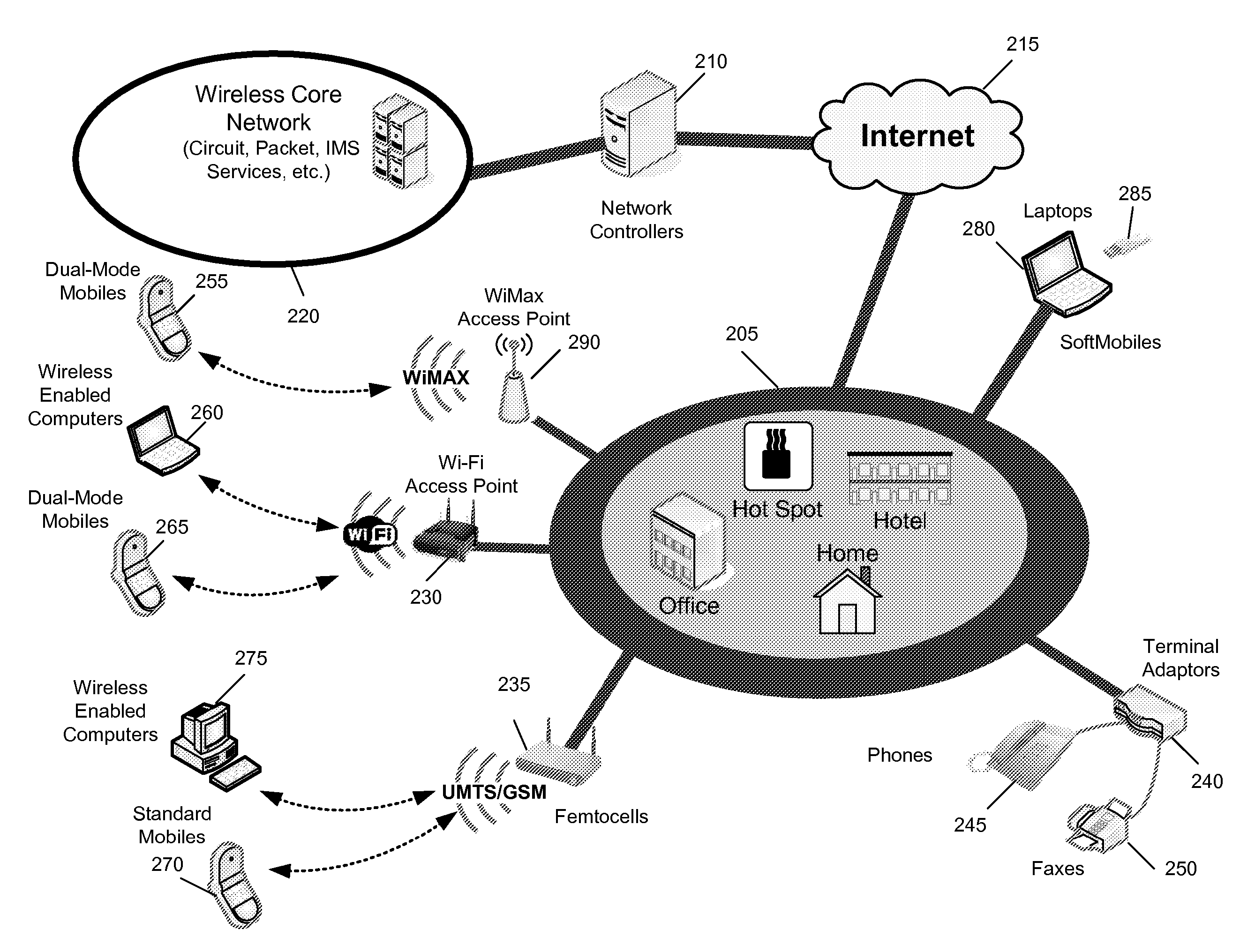
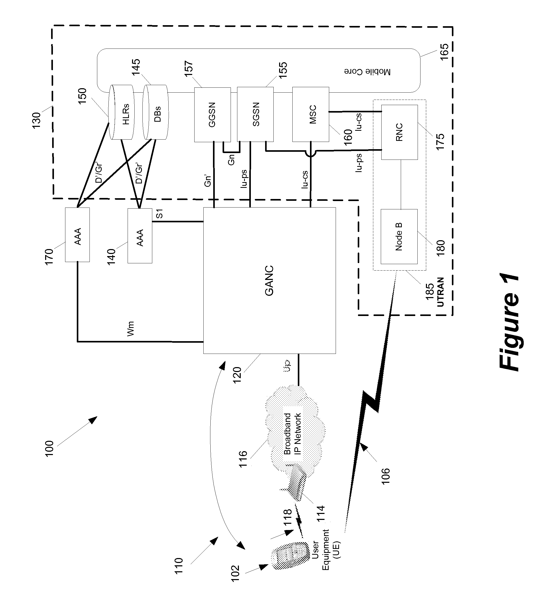
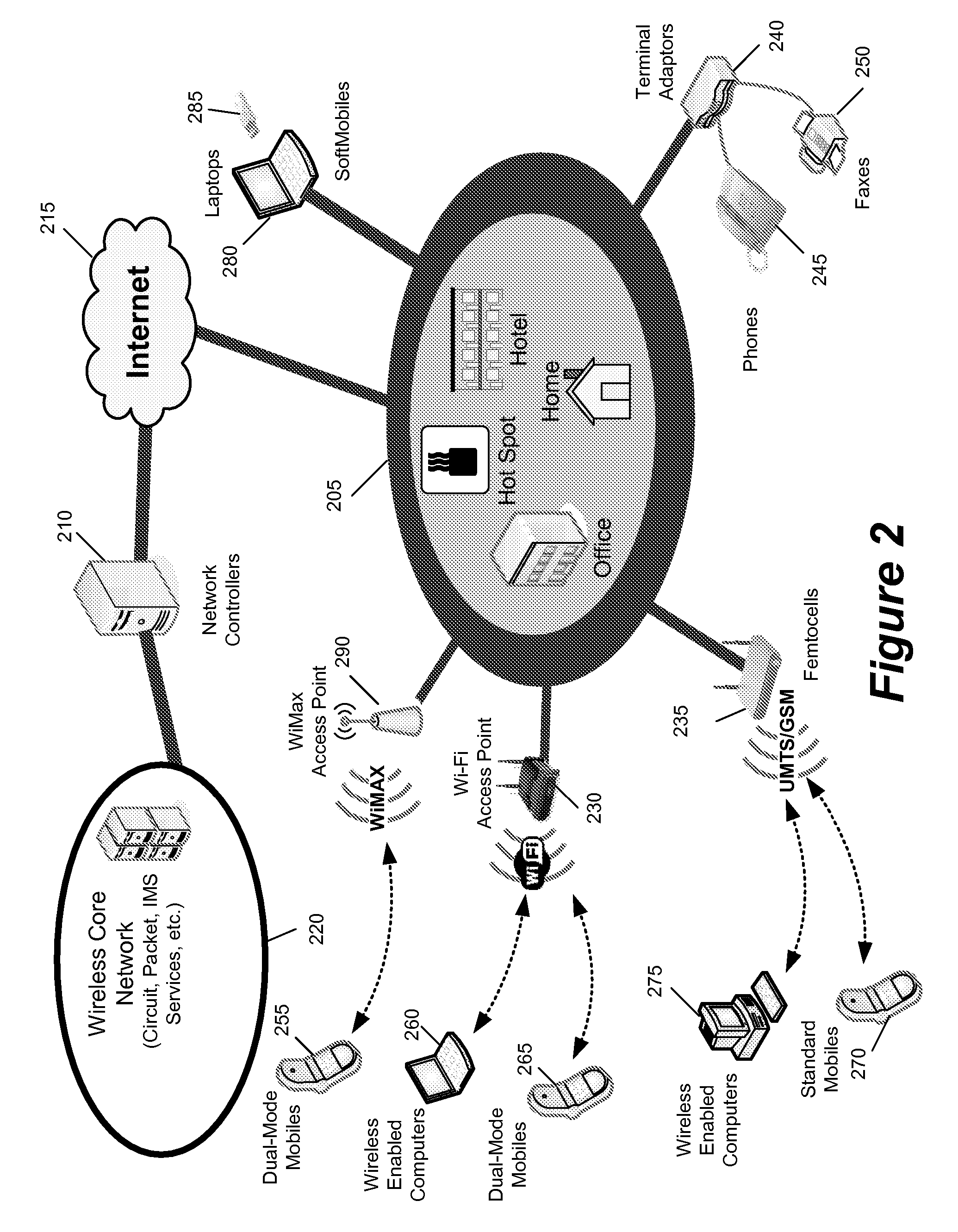
[0080] Some embodiments are implemented in a communication system that includes a first wireless communication system and a second wireless communication system that includes a Femtocell access point (FAP) and a network controller that can communicatively couple the FAP to the first wireless communication system.

[0081] In some embodiments, the net...


PUM


Abstract

Some embodiments are implemented in a communication system that includes a first wireless communication system and a second wireless communication system that includes a Femtocell access point (FAP) and a network controller that can communicatively couple the FAP to the first wireless communication system. In some embodiments, the network controller can communicatively couple to the first wireless communication system through a UTRAN Iu interface. In some embodiments, the FAP can communicatively couple to a user equipment using a short-range licensed wireless frequency. Some embodiments provide a method of performing a user equipment (UE) registration. The method establishes a unique connection dedicated to the UE between the FAP and the network controller. The method receives a register request message at the network controller from the FAP through the dedicated connection.

Description

CLAIM OF BENEFIT TO RELATED APPLICATIONS [0001] This application claims the benefit of U.S. Provisional Application 60 / 826,700, entitled “Radio Access Network—Generic Access to the Iu Interface for Femtocells”, filed Sep. 22, 2006; U.S. Provisional Application 60 / 869,900, entitled “Generic Access to the Iu Interface for Femtocells”, filed Dec. 13, 2006; U.S. Provisional Application 60 / 911,862, entitled “Generic Access to the Iu Interface for Femtocells”, filed Apr. 13, 2007; U.S. Provisional Application 60 / 949,826, entitled “Generic Access to the Iu Interface”, filed Jul. 13, 2007; U.S. Provisional Application 60 / 884,889, entitled “Methods to Provide Protection against service Theft for Femtocells”, filed Jan. 14, 2007; U.S. Provisional Application 60 / 893,361, entitled “Methods to Prevent Theft of Service for Femtocells Operating in Open Access Mode”, filed Mar. 6, 2007; U.S. Provisional Application 60 / 884,017, entitled “Generic Access to the Iu Interface for Femtocell—Stage 3”, fil...

Claims


Application Information

Patent Timeline
IPC IPC(8): H04Q7/20H04W8/04H04W76/02H04W88/06
CPCH04W8/04H04W88/06H04W84/045H04W76/02H04W76/10
Inventor KHETAWAT, AMITMARKOVIC, MILANGALLAGHER, MICHAEL D.TAO, PATRICKGUPTA, RAJEEV
Owner RIBBON COMM OPERATING CO INC
Learn More