
X-ray system and calibration method therefor

Active Publication Date: 2008-03-27
SIEMENS HEALTHCARE GMBH
View PDF2 Cites 10 Cited by
  • Summary
  • Abstract
  • Description
  • Claims
  • Application Information

AI Technical Summary

Benefits of technology

[0019] When the dark raw images and the second bright raw images are generated during the heating phase of the x-ray system, a particularly time-efficient calibration of the x-ray system is achieved.
[0020] When the first and second bright raw images and the first and second dark raw images are respectively averaged bright raw images or, respectively, dark raw images formed from a number of bright raw images or, respectively, dark raw images, random image errors are reduced.
[0022] As an alternative, the respectively required current calibration images can also first be calculated for the x-ray image generation by the quotient image belonging to the current reference temperature initially being selected and the necessary current calibration images being subsequently generated by multiplication of the first bright images with this quotient image. The storage space necessary for the calibration images is thereby reduced.

Problems solved by technology

This calibration, however, is only exactly valid for a constant temperature.
If a temperature difference exists between the point in time of the calibration (which normally is implemented after the expiration of a warm-up phase) and the point in time of the actual image acquisition (which, for example, is effected shortly after activation of the x-ray system), an error results for each detector element that is specific to this detector element, since its sensitivity no longer coincides with the sensitivity that it had during the calibration.
These differences lead to artifacts in a two-dimensional x-ray image or in a three-dimensional reconstruction.
In practice, however, a multi-point calibration for a number of reference temperatures is nearly impossible because the total duration of the calibration also increases with the increasing number of the measurement points (dose settings) used for the calibration at a reference temperature.
Such a calibration cannot be implemented in practice.

Method used


Image

  • X-ray system and calibration method therefor
  • X-ray system and calibration method therefor
  • X-ray system and calibration method therefor

Examples


Embodiment Construction

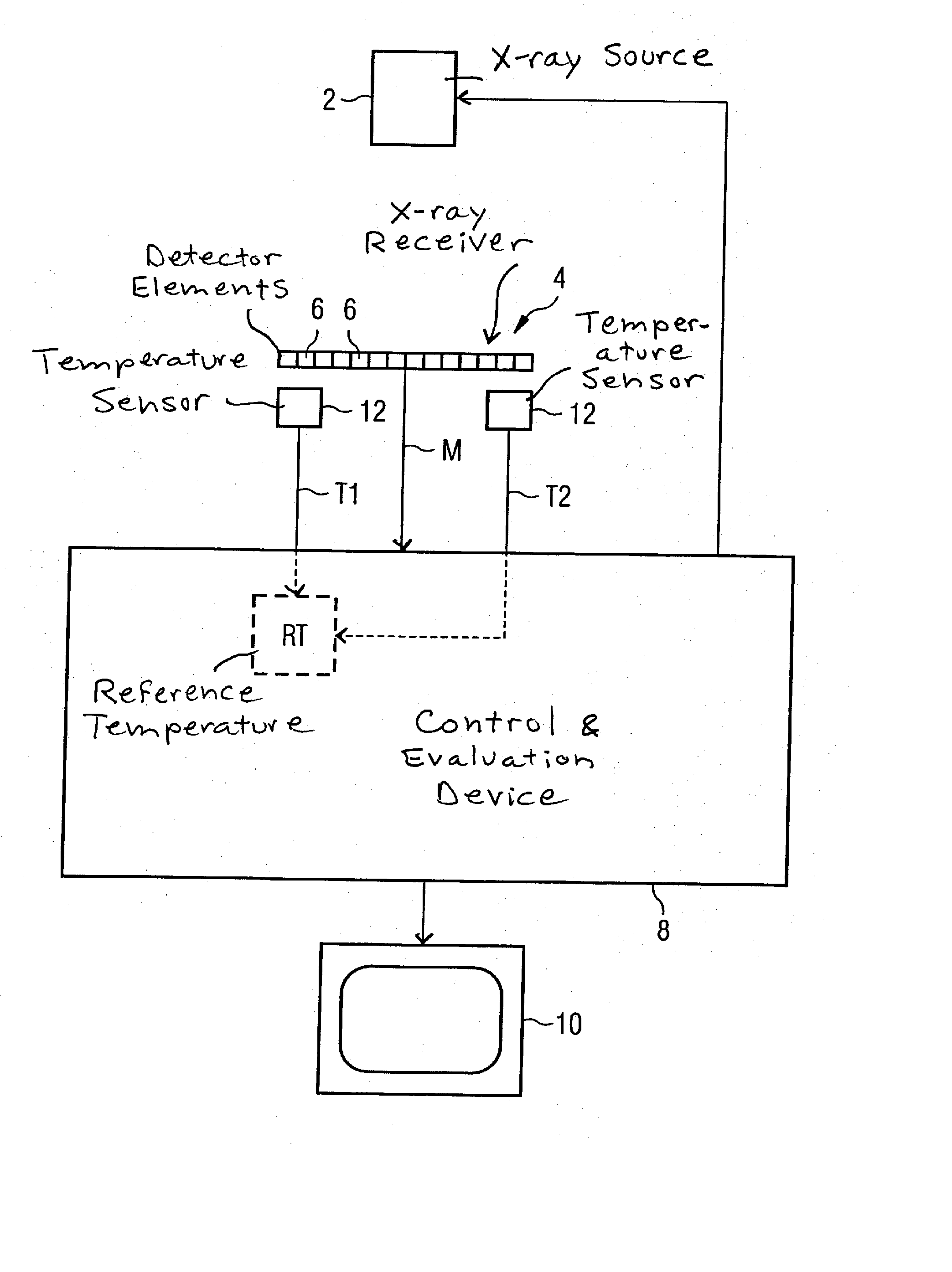
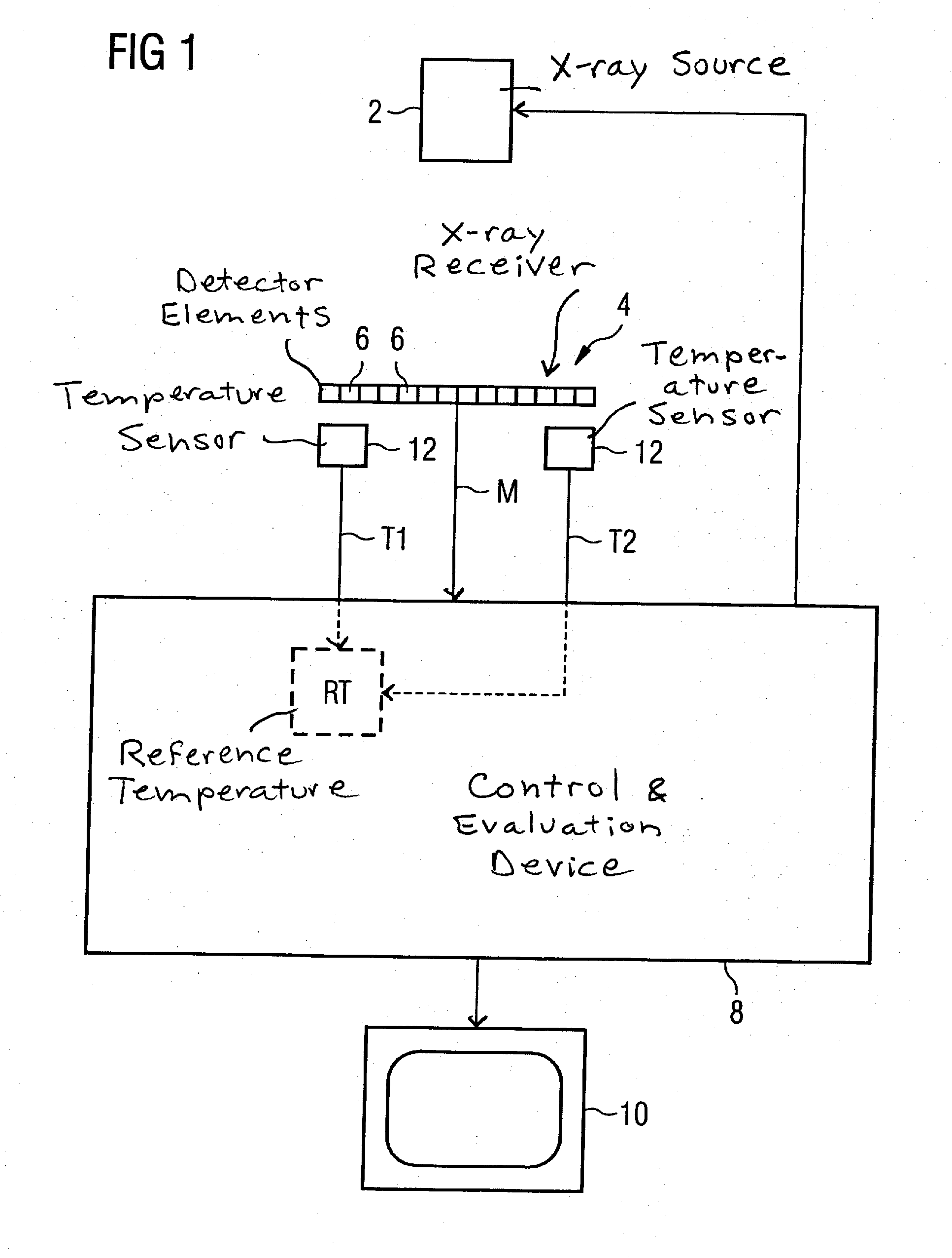
[0030] As shown in FIG. 1, the x-ray system has an x-ray source 2 as well as a digital x-ray receiver 4 having a number of detector elements 6 arranged like a matrix. X-ray source 2 and x-ray receiver 4 are connected to a central control and evaluation device 8 with which these components are controlled and the measurement signals received from the x-ray receiver 4 are evaluated. With hardware and software implemented in the control and evaluation device 8, the x-ray system can operate according to the subsequently explained method and a corrected x-ray image (correction image) that can be presented on a monitor 10 is generated.

[0031] A number of temperature sensors 12, with which the temperature distribution within the environment of the x-ray receiver 4 is measured, are arranged in the environment of the x-ray receiver 4. A reference temperature RT is determined from the temperatures T1 and T2 measured by the temperature sensors 12, of which only two are representatively drawn in...


PUM


Abstract

In a method for calibration of an image-generating x-ray system with a digital x-ray receiver and an x-ray system operating with this calibration method, a number of first offset-corrected bright images are determined at a first constant reference temperature of the x-ray receiver respective at a number first dose settings. A second offset-corrected bright image are subsequently determined at a number of second reference temperatures and at second dose settings that correspond to respective first dose settings. A quotient image is calculated from the second bright image and the first bright image for each of these reference temperatures and is stored. A multi-point calibration at various reference temperatures is implemented with low time expenditure in this manner.

Description

BACKGROUND OF THE INVENTION [0001] 1. Field of the Invention [0002] The present invention concerns a method for calibration of an image-generating x-ray system with a digital x-ray receiver. The invention moreover concerns a method for generation of an x-ray image with an x-ray system calibrated according to such a method as well as an x-ray system operating according to such a method. [0003] 2. Description of the Prior Art [0004] The digitized measurement signals (known as raw image data or raw images) generated from the detector elements of a digital x-ray receiver (which detector elements are arranged in a two-dimensional array) must be post-processed and corrected in an image processing device for reproduction of the x-ray image on a reproduction medium that is suitable for use by a radiologist from a diagnostic standpoint. In this post-processing, both the dark current component (offset) and the sensitivity (gain) must be taken into account and corrected for every single detect...

Claims


Application Information

Patent Timeline
IPC IPC(8): G06K9/00G01D18/00
CPCG03B42/02H04N5/32H04N17/002H04N5/3651H04N5/361H04N25/671H04N25/63
Inventor RITTER, DIETERSCHMIDGUNST, CHRISTIAN
Owner SIEMENS HEALTHCARE GMBH
Learn More