Case body with front panel and acoustic apparatus for vehicle use

Inactive Publication Date: 2002-09-05
JVC KENWOOD CORP A CORP OF JAPAN
View PDF0 Cites 3 Cited by
  • Summary
  • Abstract
  • Description
  • Claims
  • Application Information

AI Technical Summary

Benefits of technology

[0010] The present invention is achieved in view of the above described circumstances and has the object to provide a case body with a front panel that achieves a simplified structure and thus reduction in manufacturing cost, and allows a space in the case body to be effectively used.

Problems solved by technology

However, in the above described case body with a front panel, the operation panel is pivoted by means of the gear in the driving mechanism in the case body, which causes problems that the apparatus requires a complex structure such as where the driving mechanism has to be moved forward and backward to thereby result in an increase in manufacturing cost.
There is also a problem that a space in the case body cannot be effectively used since a space where the driving mechanism can be moved forward and backward have to be secured in the case body.

Method used


Image

  • Case body with front panel and acoustic apparatus for vehicle use
  • Case body with front panel and acoustic apparatus for vehicle use
  • Case body with front panel and acoustic apparatus for vehicle use

Examples


first embodiment

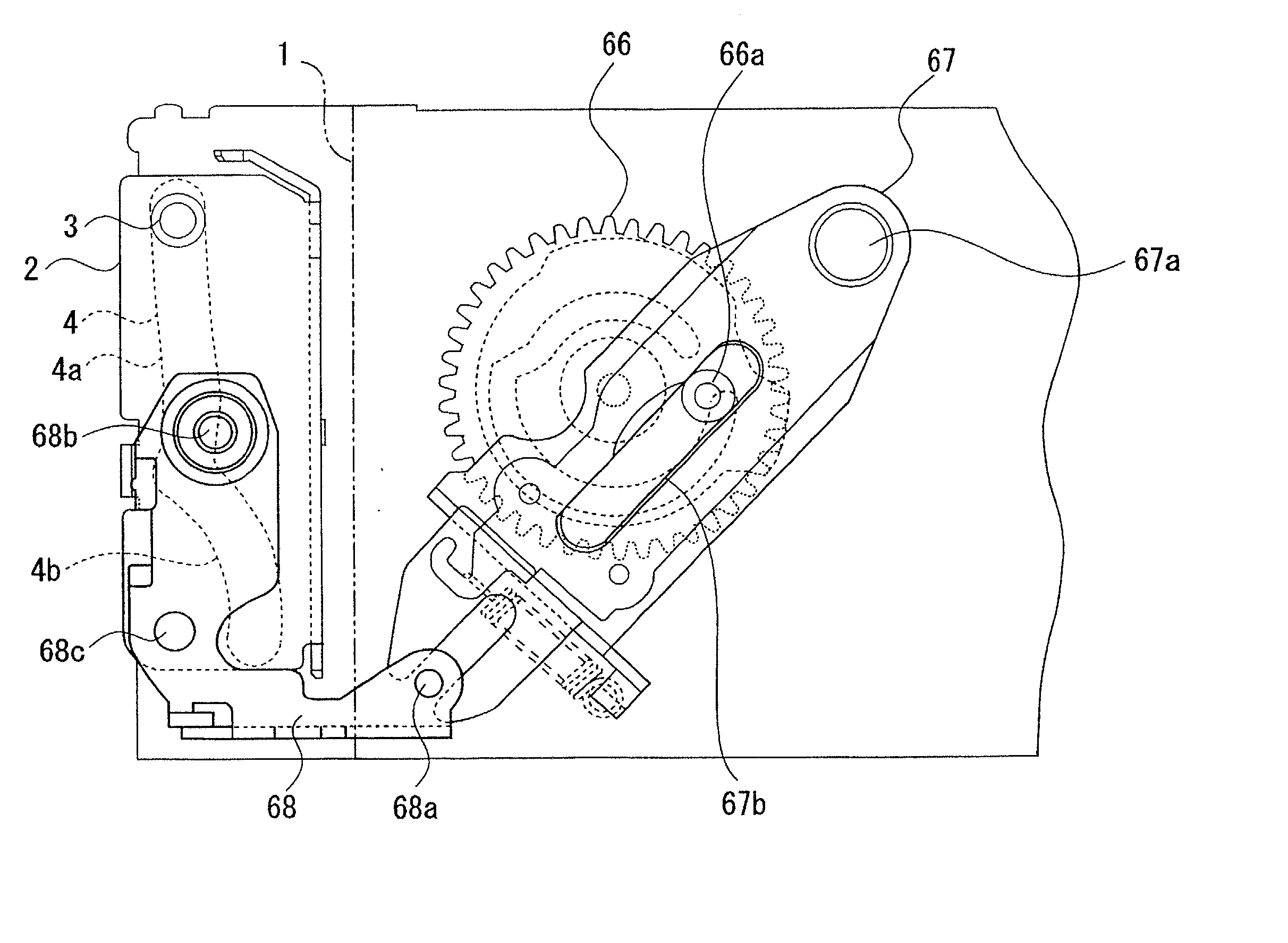
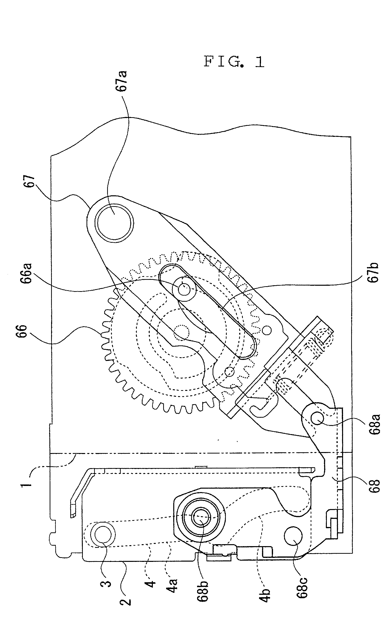
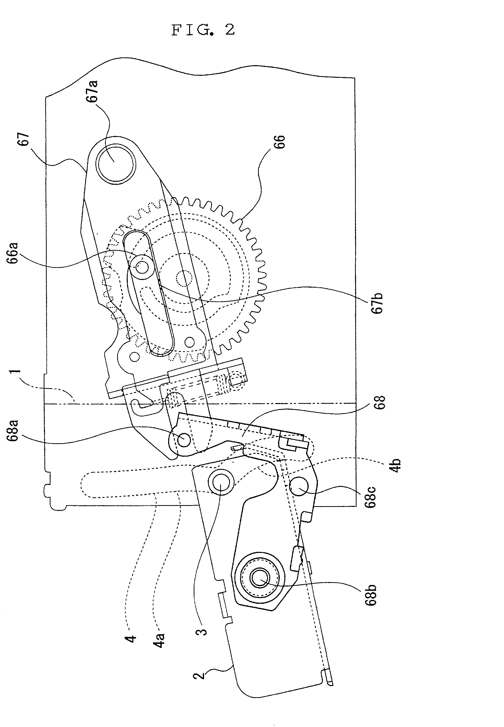
[0041] FIGS. 1 to 6 show the present invention, and are side views, partially in perspective, of a case body with a front panel.

[0042] The case body with a front panel is used, for example, for an acoustic apparatus for vehicle use, and comprises a box-like case body 1 and an operation panel 2 located on a front side of the case body 1 as shown in FIG. 1. The operation panel 2 is provided, at its top, with a shaft member 3, which is guided by a groove 4 formed on the case body 1. As shown in FIG. 4, a DC motor 5 is arranged in the case body 1, and a driving mechanism 6 is provided that transmits a driving force of the DC motor 5 to the operation panel 2. That is, the DC motor 5 and the driving mechanism 6 form driving means in this embodiment.

[0043] The case body 1 is mounted to an instrument panel of a vehicle with its front surface inward, and can hold a recording medium such as CD (Compact Disk) or MD (Mini Disk) inserted from an insertion port (not shown) formed on the front sur...

second embodiment

[0062] FIGS. 7 to 9 show the present invention, and are side views, partially in perspective, of a case body with a front panel.

[0063] The case body with a front panel is used, for example, for an acoustic apparatus for vehicle use, and comprises a box-like case body 101 and an operation panel 102 located on a front side of the case body 101 as shown in FIG. 7. The operation panel 102 is provided, at its top, with a shaft member 103, which is guided by a groove 104 formed on the case body 101. A DC motor (not shown) is arranged in the case body 101, and a driving mechanism that is provided that transmits a driving force of the DC motor to the operation panel 102. That is, the DC motor and the driving mechanism form driving means in this embodiment.

[0064] The case body 101 is mounted to an instrument panel of a vehicle with its front surface inward, and can hold a recording medium such as CD (Compact Disk) or MD (Mini Disk) inserted from an insertion port (not shown) formed on the fr...


PUM


Abstract

To provide a case body with a front panel that achieves a simplified structure and thus reduction in manufacturing cost, and allows a space in the case body to be effectively used. There is provided a case body with a front panel in which driving means is actuated to thereby cause an attitude of a panel 2 to be successively changed from a first state where the panel 2 is substantially parallel to a front surface of a case body 1, to a second state where the panel 2 substantially horizontally projects forward from the front surface of the case body 1, and to a third state where top and bottom as well as inside and outside of the panel 2 are reversed to the first state, wherein the driving means has a panel driving member 68 pivotably coupled to the panel via a drive shaft 68b, and as the drive shaft 68b moves, the shaft member 3 moves in the groove 4 to pivot the panel 2.

Description

BACKGROUND OF THE INVENTION[0001] 1. Field of the Invention[0002] The present invention relates to a case body with a front panel having a panel on a front side of a case body.[0003] 2. Related Background Art[0004] Known conventional acoustic apparatuses for vehicle use of this type generally use case bodies with front panels as shown in FIGS. 10 to 12. FIGS. 10 to 12 are side views, partially in perspective, of the case body with a front panel.[0005] This case body with a front panel comprises a box-like case body 201 and an operation panel 202 located on a front side of the case body 201 as shown in FIG. 10. An attitude of the operation panel 202 is successively changed from an operation state of being substantially parallel to a front surface of the case body 201 as shown in FIG. 10, to an EJECT state of substantially horizontally projecting forward from the lower other end of the front surface of the case body 201 as shown in FIG. 11, and to an OFF state where top and bottom as ...

Claims


Application Information

Patent Timeline
IPC IPC(8): B60R11/02G05B11/01G11B17/04G11B33/02
CPCB60R11/02G05B11/01G11B33/02G11B17/04G11B33/027
Inventor AOKI, MASAYOSHI
Owner JVC KENWOOD CORP A CORP OF JAPAN
Why Eureka
Try Eureka