Eureka AIR delivers breakthrough ideas for toughest innovation challenges, trusted by R&D personnel around the world.

Switching regulator, transceiver circuit, and keyless access control system

a transceiver circuit and switch technology, applied in the field of switch regulators, can solve the problems of increasing parasitic capacitances and inductances, no longer negligible, and difficulty in controlling the plurality of antennas, and achieve the effect of stabilizing the regulation respons

Active Publication Date: 2008-03-27
ATMEL CORP
View PDF20 Cites 10 Cited by
  • Summary
  • Abstract
  • Description
  • Claims
  • Application Information

AI Technical Summary

Benefits of technology

[0013] It is therefore an object of the present invention to provide an alternative, improved regulation in a switching regulator, which provides primarily as stable a regulation response as possible also at highly varying output voltages.
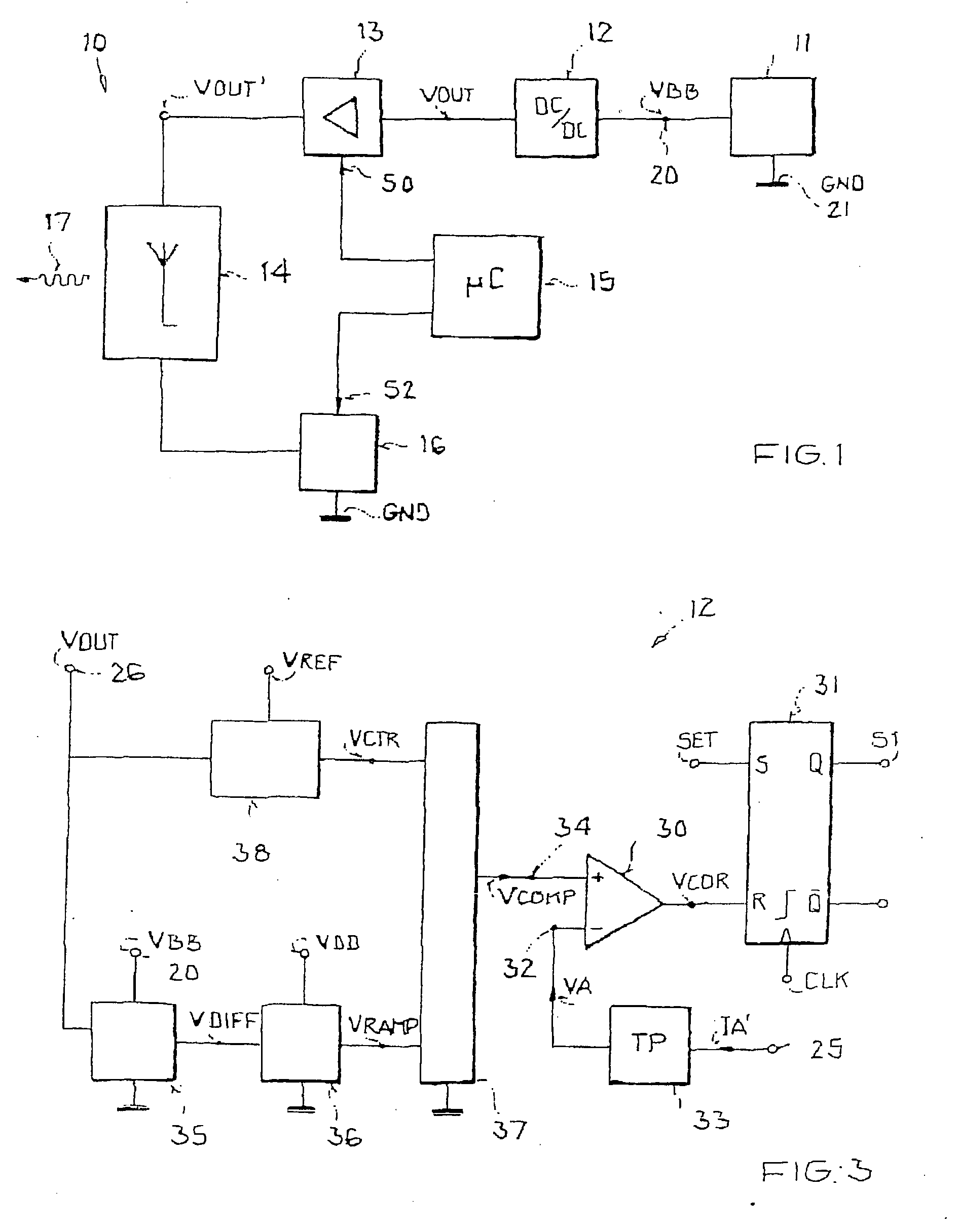
[0016] An object of the present invention is to measure both an input voltage and an output voltage that determines the coil current slope in an antenna circuit. On their basis, a voltage difference is calculated which determines the steepness of a ramp of an internal compensation signal within the switching regulator. On the basis of this internal compensation signal, a constant current is determined that is added to the output signal to reduce the effect of the voltage drop across the antenna coil. A very stable regulation response overall is obtained thereby due to a constant pulse duty factor; i.e., this achieves a very stable output voltage across the antenna coil and thus a constant antenna current.
[0017] Because of the very stable, constant pulse duty factor, an improved EMC behavior also results advantageously during use of a switching regulator of the invention or a corresponding transceiver circuit with a switching regulator of this type.

Problems solved by technology

It is problematic here that as the length of the connecting lines increases, their parasitic capacitances and inductances also increase, so that these are no longer negligible.
Another problem results from the type of transmit antennas, which ideally are to be made as identical as possible, but which in the specific technical implementation, e.g., due to the employed production technology, in fact have a more or less broad variation in the antenna impedance.
The control of the plurality of antennas is problematic here.
The particular problem here is that the switching regulator can thereby become unstable in its control stability, which overall has the result that a functioning control is no longer assured.

Method used


Image

  • Switching regulator, transceiver circuit, and keyless access control system
  • Switching regulator, transceiver circuit, and keyless access control system
  • Switching regulator, transceiver circuit, and keyless access control system

Examples


Embodiment Construction

[0042] In the figures of the drawing, the same and functionally identical elements, features, and signals, if not specified otherwise, are provided with the same reference characters.

[0043] The invention relates to a preferably fully integrated circuit arrangement for setting the compensation ramp, necessary for stable control operation of a switching regulator, of a current-operated switching regulator, such as, for example, a boost converter. Switching regulators of this type are often also called CCM (CCM=continuous current mode) boost converters in the literature. To attain the most stable regulation response possible of the switching regulator and thereby a constant pulse duty factor, the ratio necessary for the switching regulator between the actual antenna current (ΔIA / Δt) and the internal ramp of the compensation signal must be suitably set. Because of the aforementioned additional condition, to be able to use the largest range possible for the antenna impedance (generally ...


PUM


Abstract

A switching regulator for controlling transmit antennas of variable impedance, particularly transmit antennas of a keyless access authorization system in or for a vehicle, having an input terminal into which an antenna potential applied or appliable at the transmit antenna may be coupled, and having a control circuit designed to generate a compensation signal as a controlled variable for adapting the antenna potential to an actual output impedance and to establish a slope of the compensation signal depending on the actual antenna potential. The invention relates furthermore to a transceiver circuit with such a switching regulator and to a keyless access control system in or for a vehicle.

Description

[0001] This nonprovisional application claims priority to German Patent Application No. DE 102006038936, which was filed in Germany on Aug. 18, 2006, and to U.S. Provisional Application No. 60 / 838,376, which was filed on Aug. 18, 2007, and which are both herein incorporated by reference.BACKGROUND OF THE INVENTION [0002] 1. Field of the Invention [0003] The present invention relates to a switching regulator for controlling transmit antennas of variable impedance, particularly transmit antennas of a keyless access authorization system in or for a vehicle, a transceiver circuit having a switching regulator of this type, and a keyless access control system in or for a vehicle. [0004] 2. Description of the Background Art [0005] The invention and its underlying problem are described hereafter with reference to a keyless access control system in a motor vehicle, however, without limiting the invention thereto. It is pointed out in particular that the invention may certainly also be used i...

Claims


Application Information

Patent Timeline
Patent Type & Authority Applications(United States)
IPC IPC(8): G08B29/00
CPCH04B1/04G07C9/00944
Inventor REBHOLZ-GOLDMANN, PETER
Owner ATMEL CORP
Why Eureka
Eureka Blog
Learn More