Line analyzer with automatic pair combination sequencing

Inactive Publication Date: 2008-03-27
BARSUMIAN BRUCE R +1
View PDF4 Cites 4 Cited by
  • Summary
  • Abstract
  • Description
  • Claims
  • Application Information

AI Technical Summary

Benefits of technology

[0006] An embodiment of the present invention is directed toward a method of identifying line anomalies in a multiple conductor cable with a line analyzer. In accordance with the method, a switching matrix is determined that specifies a plurality of wire pair combinations and switching instructions for automatically coupling the line analyzer to each of the plurality of wire pair combinations. A test is performed on each of the wire pair combinations specified by the switching matrix to obtain test data for each pairing combination and between each conductor and earth ground. Alternatively, any balanced wire pairs in the wire pairs specified by the switching matrix can be automatically identified and the test only performed on the balanced wire pairs. Typically, balanced wire pairs consist of conductors that are twisted together to maintain a desired transmission line impedance to minimize signal loss and noise. The tests may include, but are not limited to, multi-meter type measurements such at voltage, current, resistance, and capacitance; AC voltage level, audio and video content; non-linear junction detection; RF detection; and frequency and time domain reflectometry operations. A table or graph of the test data is then displayed for use in identifying any line anomalies. The test data is also mathematically compared by the analyzer to further aid in identifying line anomalies.

Problems solved by technology

This becomes exponentially more complex as the number of wires increases.
Reconfiguring the analyzer for each test is time consuming and increases the likelihood that an error will occur in carrying out the test procedure.
A further complicating factor is the enormous number of communications lines that may exist in a location or system to be examined.

Method used


Image

  • Line analyzer with automatic pair combination sequencing
  • Line analyzer with automatic pair combination sequencing
  • Line analyzer with automatic pair combination sequencing

Examples


Embodiment Construction

[0018] The present invention is directed toward an improved process for detecting taps, wiring or electronics that may be coupled to a multiple conductor cable. The process can be applied to any type of multiple conductor wiring that is carrying information or power such as data lines, LAN lines, telephone lines, power lines, etc. The present invention is particularly advantageous over the prior are with respect to automatically analyzing communication cables with multiple conductors to detect any surreptitious electronics coupled to a non-standard conductive wire pair of the cable or coupled to any of the conductors and an earth ground.

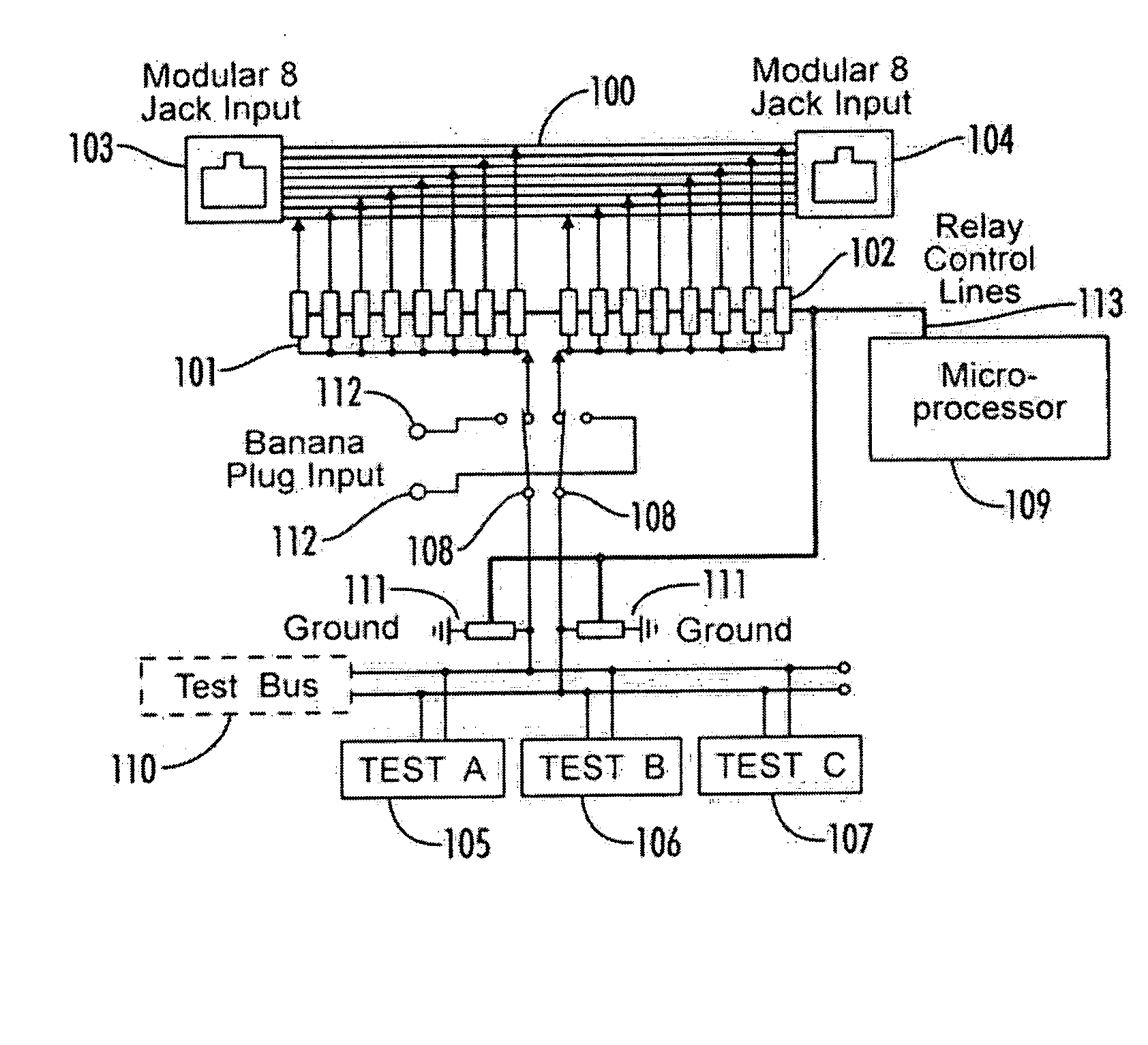
[0019]FIG. 1 is a block diagram of a test setup using arrays of reed relays to implement a switching matrix in accordance with an embodiment of the present invention. As shown in FIG. 1, two arrays 101 and 102 of eight reed relays each are connected to an eight conductor bus 100 which is in turn coupled to an eight conductor modular input 103 and ou...


PUM


Abstract

A line analyzer for detecting line anomalies that may be indicative of electronic tape or other surveillance related electronics coupled to a wire pair in a multiple conductor cable utilizes a switching matrix to identify possible pairings of the conductors and instruct the analyzer to selectively couple to each of the identified conductor pairings. Tests such as non-linear junction detection and frequency or time domain reflectometry operations are automatically performed on each of the wire pairs by the analyzer. The analyzer can automatically identify balanced pairs and limit the testing to the identified balanced pairs to minimize the time required for testing if desired. The results are then mathematically and graphically compared to identify wires having line anomalies. The tests can be performed over time intervals to locate transient anomalies.

Description

CROSS-REFERENCE TO RELATED APPLICATIONS [0001] The present application is a continuation-in-part of, and claims priority from, co-pending U.S. patent application Ser. No. 11 / 266,020 filed Mar. 3, 2007 which is a divisional of U.S. patent application Ser. No. 11 / 266,538 filed Nov. 3, 2005 and U.S. patent application Ser. No. 11 / 782,636 filed Jul. 25, 2007.STATEMENT REGARDING FEDERALLY SPONSORED RESEARCH OR DEVELOPMENT [0002] Not Applicable. REFERENCE TO SEQUENCE LISTING OR COMPUTER PROGRAM LISTING APPENDIX [0003] Not Applicable. FIELD OF THE INVENTION [0004] The present invention is directed generally toward a line analyzer that has automated line evaluation software and circuitry that sequences through possible line pair combinations in a multiple conductor cable. BACKGROUND OF THE INVENTION [0005] Line analyzers have previously been used to detect line parameters and couplings. These analyzers are typically coupled to a wire or wire pair being tested. A set of line parameters are t...

Claims


Application Information

Patent Timeline
IPC IPC(8): G01R27/28
CPCH04B3/46H04M2203/6027H04M3/308H04M3/305
Inventor BARSUMIAN, BRUCE R.JONES, THOMAS H.
Owner BARSUMIAN BRUCE R
Why Eureka
Try Eureka