
Symmetrized coupler converting circular waveguide TM01 mode to rectangular waveguide TE10 mode

a technology of asymmetric coupler and asymmetric waveguide, which is applied in the direction of waveguide type devices, coupling devices, basic electric elements, etc., can solve the problems of reducing the number of couplers, destroying the entire device, and not eliminating the problem of unwanted effects

Inactive Publication Date: 2008-03-20
DULY RES
View PDF8 Cites 13 Cited by
  • Summary
  • Abstract
  • Description
  • Claims
  • Application Information

AI Technical Summary

Benefits of technology

"The present invention provides a device that can convert rf power in one mode to another mode in a waveguide. The device has a symmetrized coupler that reduces unwanted modes and has a better bandwidth and transmission coefficient compared to prior art couplers. The coupler can be used in applications such as high power applications and can provide a high quality of nearly single-mode operation. The transformation of the rf waves into dipole and quadrupole modes is significantly reduced compared to conventional designs. The coupler can have one, two, or four standard rectangular ports and can be fabricated using metal, copper being the preferred material. The overvoltage is very moderate, allowing for the use of the coupler in high power applications. The device can be used to feed rf power from a rectangular waveguide to a linear electron accelerator or for extracting rf power from an electronic vacuum or plasma device."

Problems solved by technology

Typical coupler designs always have some transformation of the fundamental operational mode into unwanted modes which may narrow bandwidth and, if an electron beam is present, can also drive dangerous instabilities (such as notable “beam break-up”) that can eventually destroy the entire device.
The symmetrized couplers lessen but do not eliminate the problem of unwanted modes.
Such a mode trapped in the coupler can degrade the performance of the whole device assembly.

Method used


Image

  • Symmetrized coupler converting circular waveguide TM01 mode to rectangular waveguide TE10 mode
  • Symmetrized coupler converting circular waveguide TM01 mode to rectangular waveguide TE10 mode
  • Symmetrized coupler converting circular waveguide TM01 mode to rectangular waveguide TE10 mode

Examples


Embodiment Construction

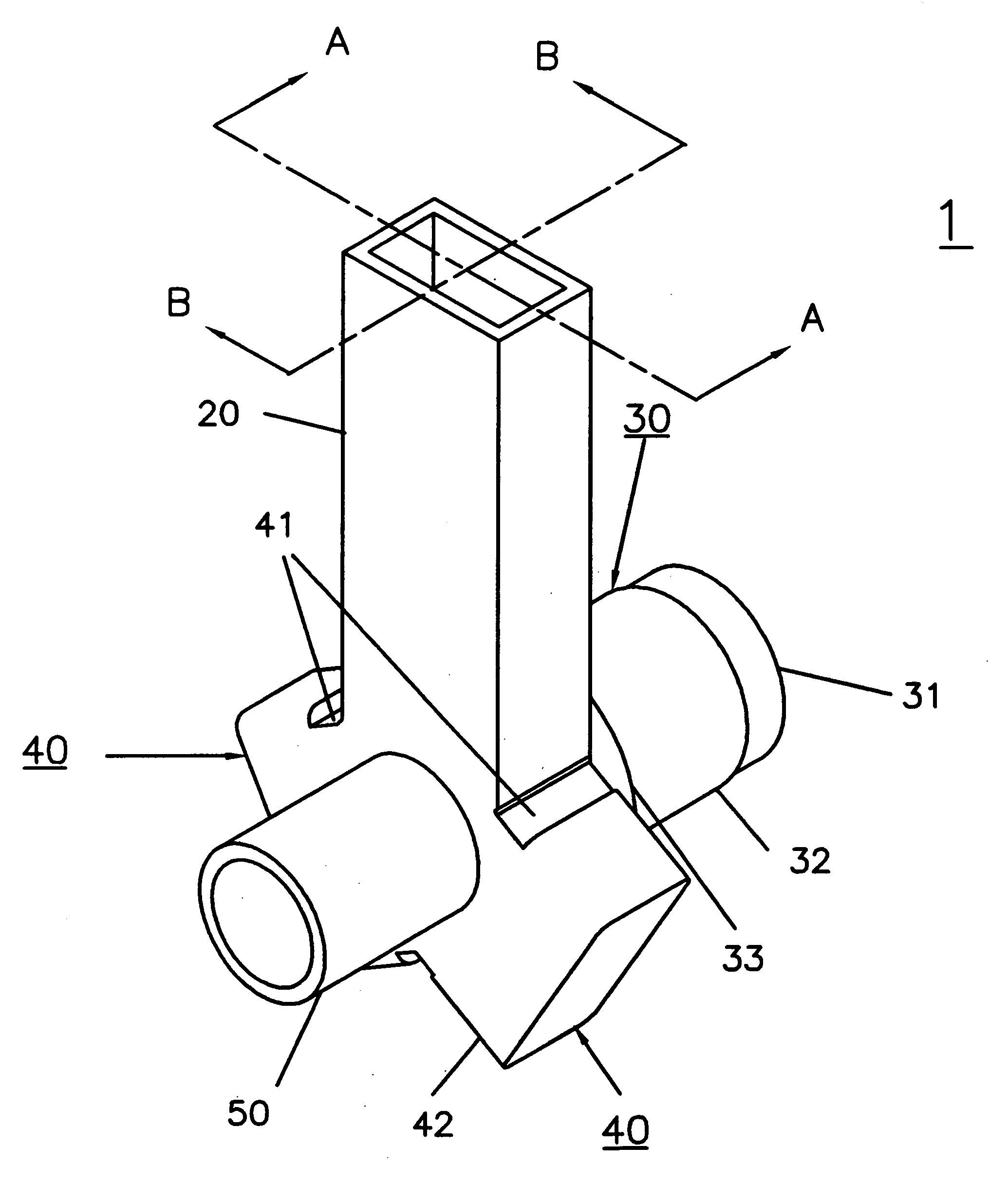
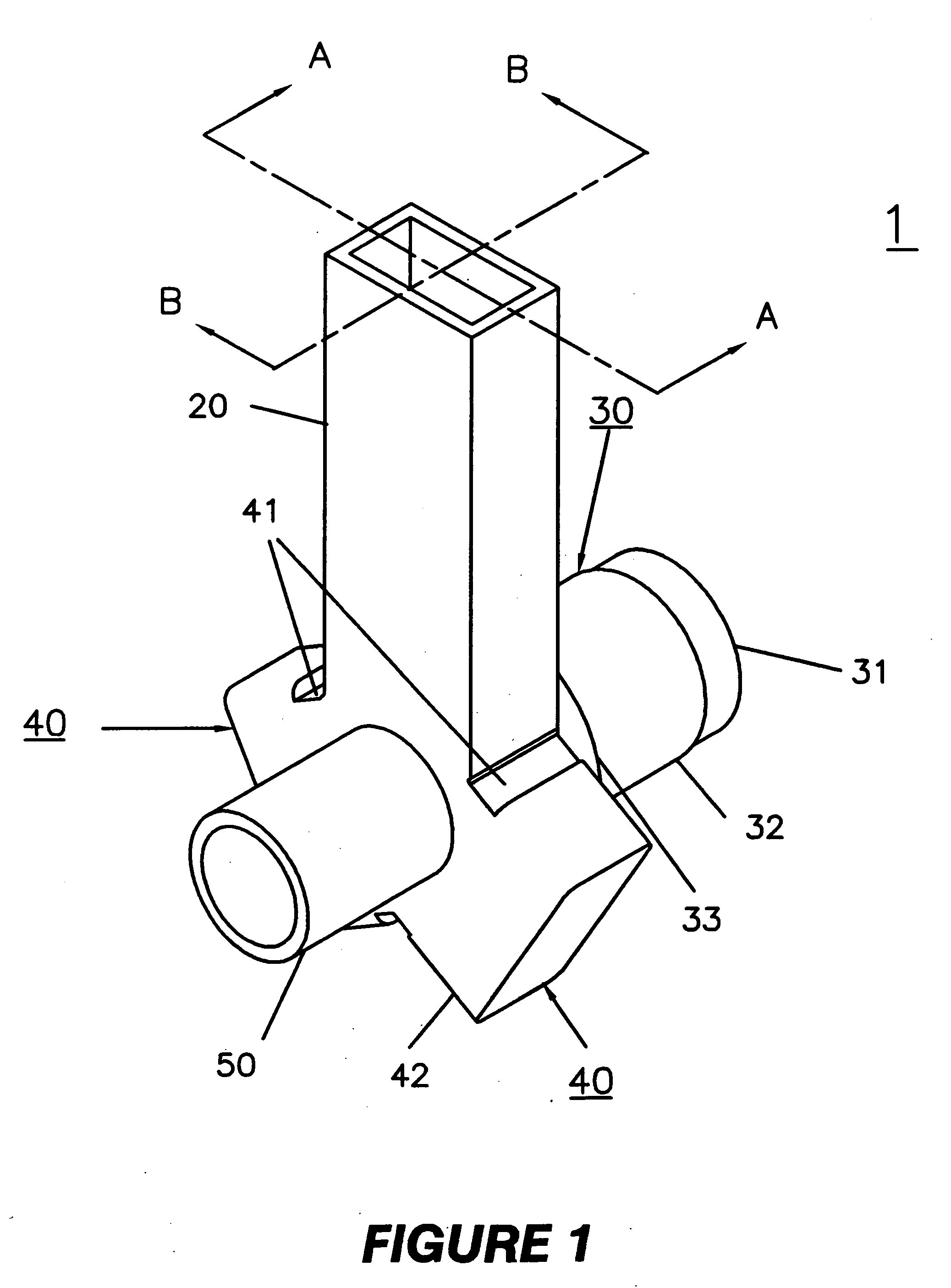
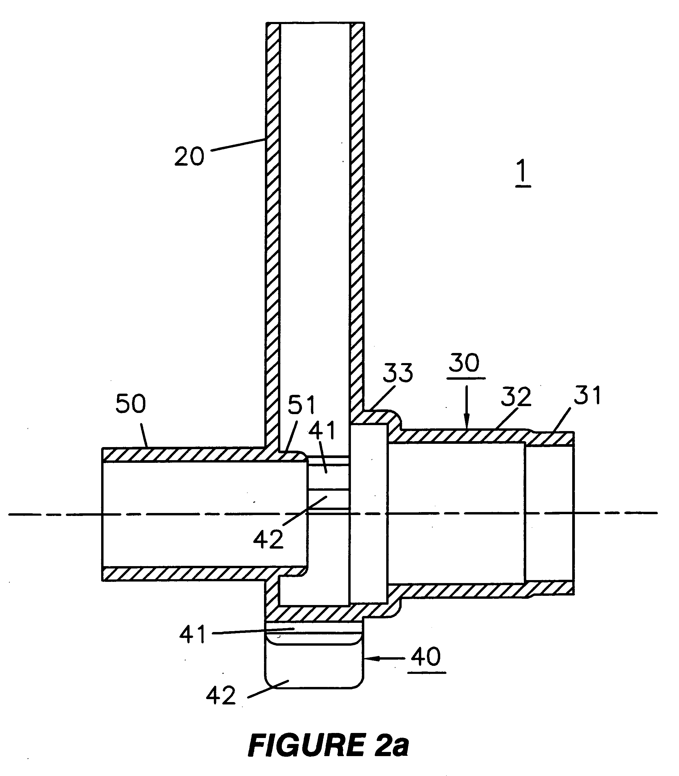
[0023]Referring to FIGS. 1, 2a and 2b, the first embodiment of the coupler 1 of the present invention is illustrated. FIG. 2a is a view at a mid section of the coupler 1 parallel to the axis of the circular waveguide 30. FIG. 2b is a view at a mid section perpendicular to the axis of the circular waveguide 30. The single arm coupler 1 comprises a rectangular waveguide 20, a circular waveguide 30, two rectangular stubs 40, an evanescent pipe 50, and an extension ring 51 of the evanescent pipe 50, which protrudes into the circular waveguide 30. In the design illustrated in FIGS. 1 and 2, the circular port 31 of waveguide 30 has a diameter exceeding the cutoff dimension of the TM01 mode by only a few percent. This requires three sections in the circular waveguide 30: the port end 31 of waveguide 30 having the smallest diameter, the mid-section 32 having a larger diameter, and the third section 33, containing the junction area of the coupler components, having the largest diameter. The ...


PUM


Abstract

A coupler for converting rf power traveling in the TM01 mode in a circular waveguide to the TE10 mode in a rectangular waveguide. The circular waveguide has an extension comprising an evanescent tube through the coupler allowing the propagation of a particle beam but disallowing the propagation of rf wave in the tube.

Description

GOVERNMENT RIGHTS [0001]This invention was made with government support under Grant No. DE-FG03-01ER83232 awarded by the Energy Department. The government may have certain rights in the invention.BACKGROUND OF THE INVENTION[0002]1.Field of the Invention[0003]The present invention provides a coupler for converting a radiofrequency (rf) TM01 mode wave traveling in a circular waveguide to a TE10 mode in a rectangular waveguide, and converting a TE01 mode in a rectangular waveguide to a TM01 mode in a circular waveguide.[0004]2. Description of Prior Art[0005]For many applications, a device to transmit radiofrequency (rf) power efficiently between a waveguide operating in a circular TM01 mode and a perpendicular waveguide (or waveguides) operating in a rectangular TE10 mode is needed. Ideally, such a passive device should not have reflections in a broad band of operation. In addition, in many cases it must have an additional (outlet) port allowing no rf power flow, placed along the same ...

Claims


Application Information

Patent Timeline
Patent Type & Authority Applications(United States)
IPC IPC(8): H01P1/163
CPCH01P5/082
Inventor SMIRNOV, ALEXEI V.YU, DAVID U.L.
Owner DULY RES
Learn More