
Suspended ceiling grid network utilizing seismic separation joint clips

a grid network and suspended ceiling technology, applied in ceilings, walls, flooring, etc., can solve the problems of inability to use grid members with such wide flanges, affecting the aesthetic appeal of the overall grid network, and reducing the possibility of displacemen

Active Publication Date: 2008-03-13
WORTHINGTON ARMSTRONG VENTURE
View PDF9 Cites 63 Cited by
  • Summary
  • Abstract
  • Description
  • Claims
  • Application Information

AI Technical Summary

Benefits of technology

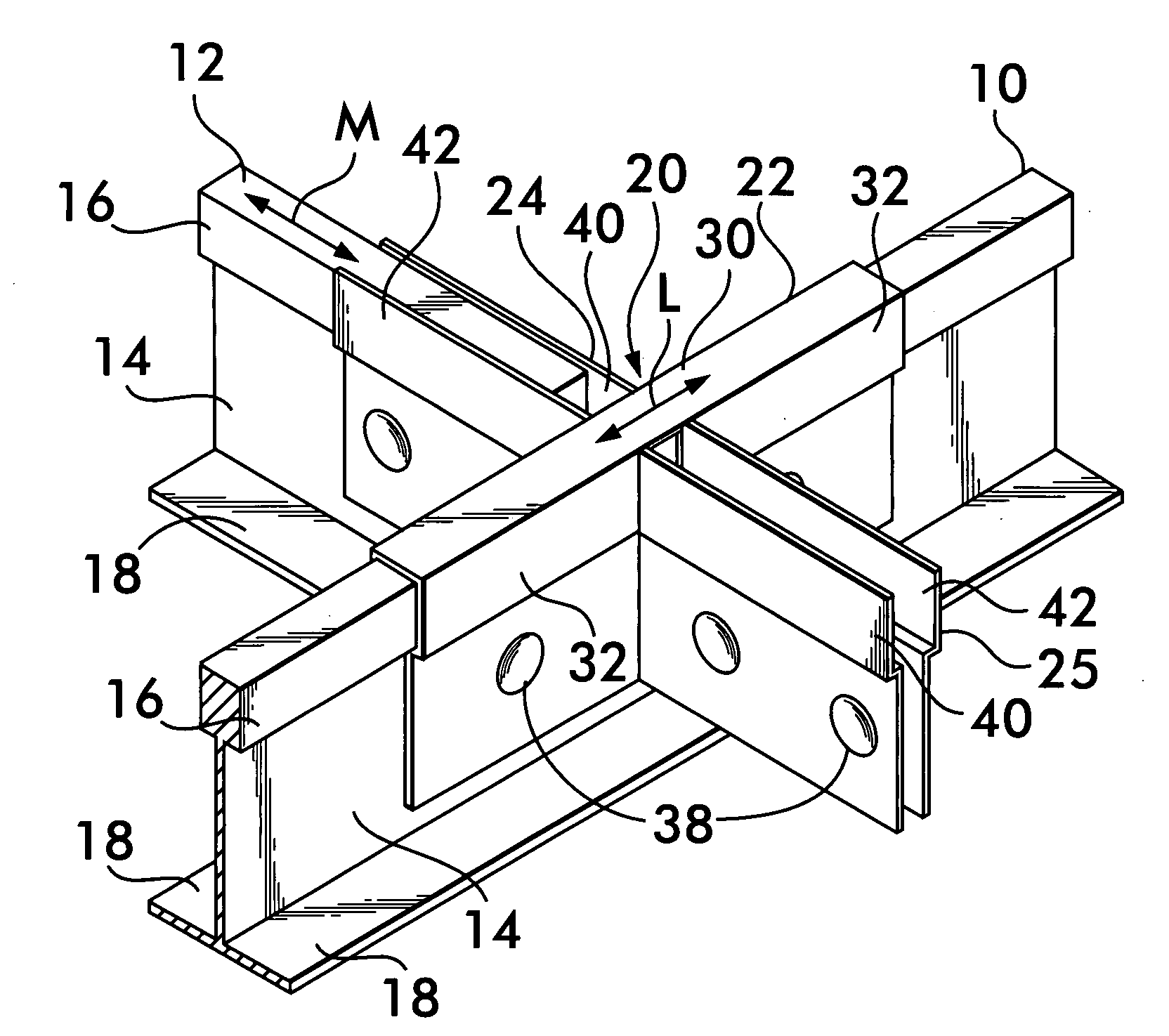
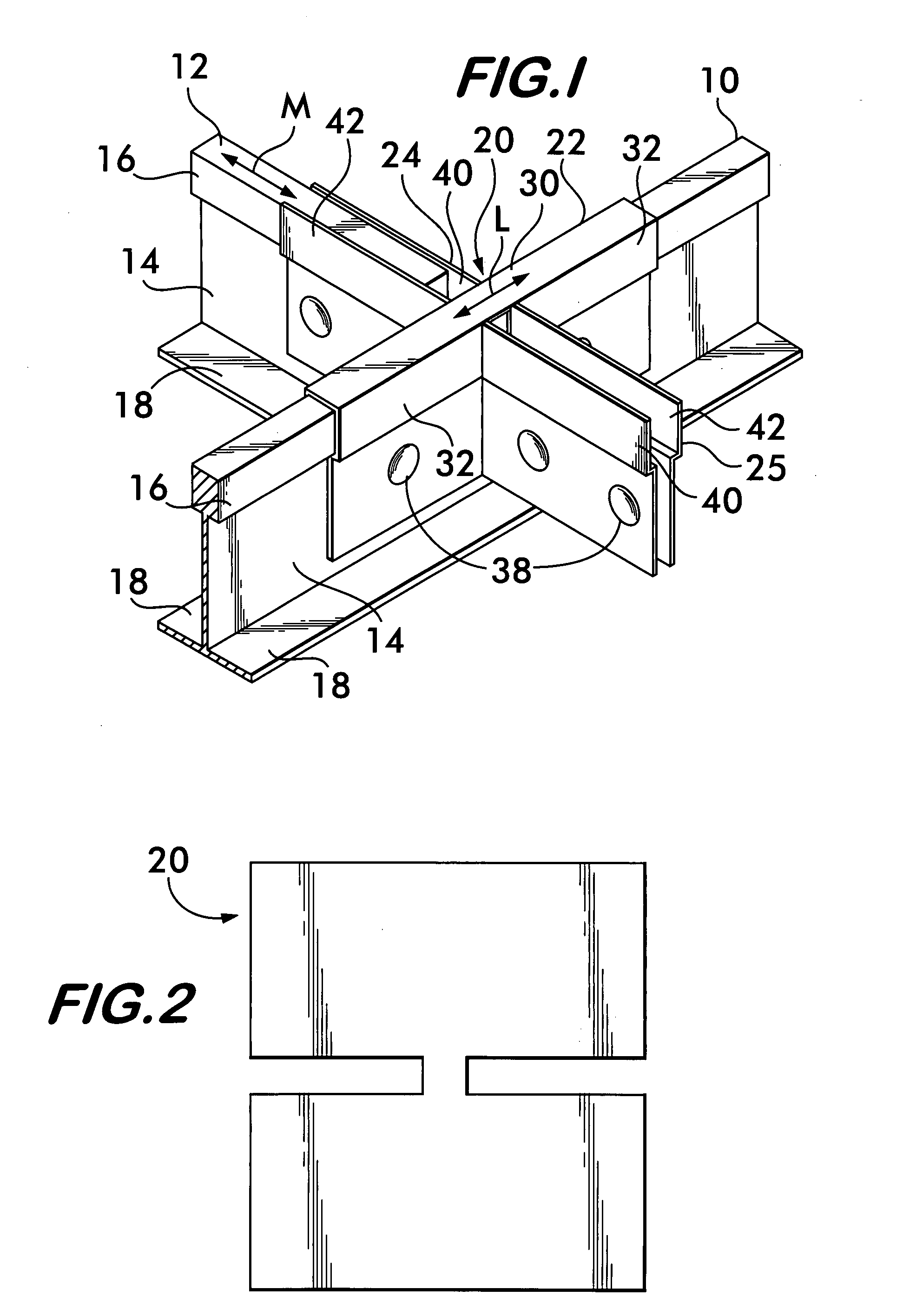
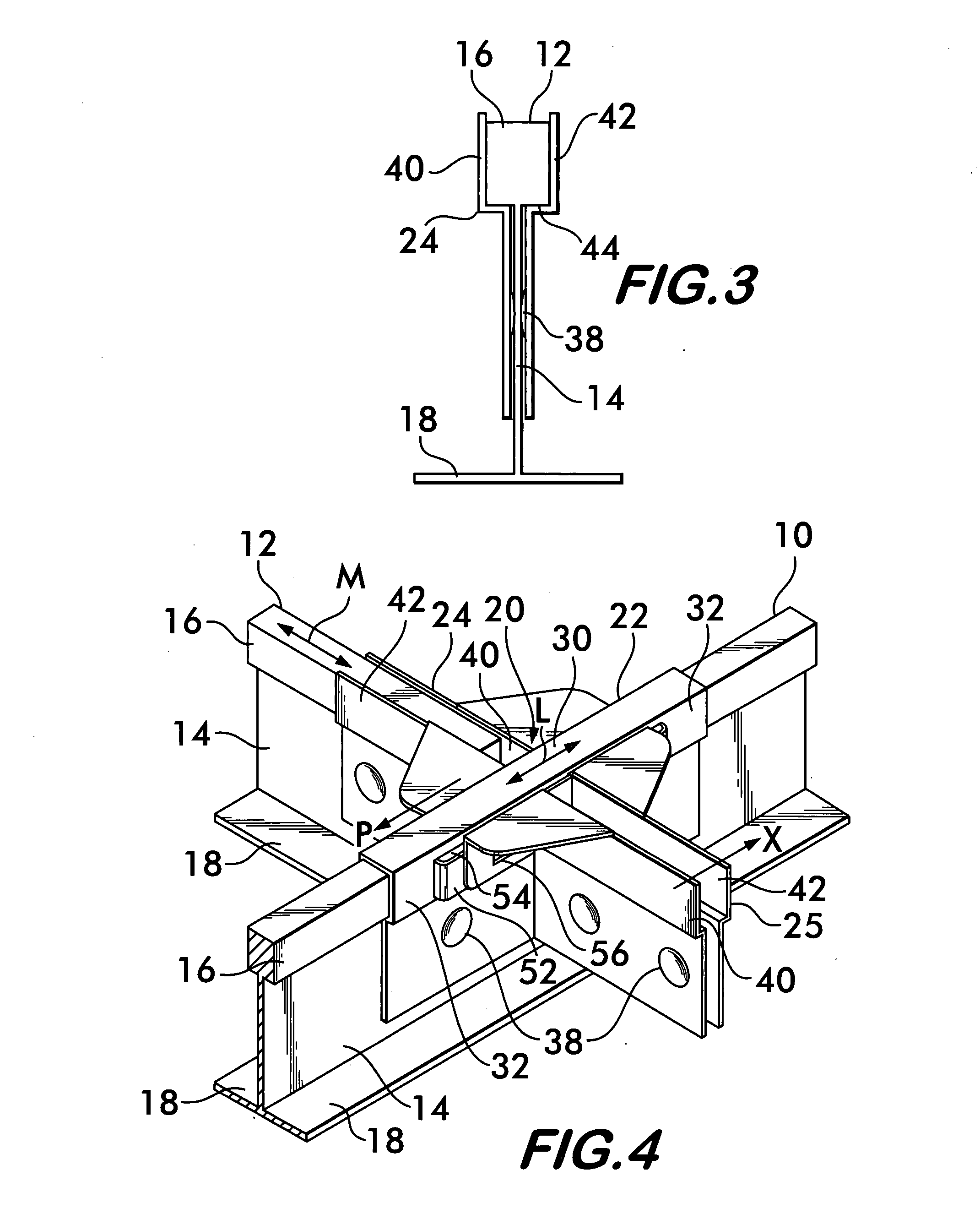
[0012]In the embodiments disclosed, the joint clips of the invention partition the primary grid network into smaller networks, or islands. Each smaller grid network or island, is capable of moving independently of neighboring grid networks, or islands, while at the same time, preserving the aesthetic appeal of the overall grid network. The clip adds structural strength to the overall grid framework to prevent twisting and withdrawal of the cross grid members from the primary grid member.

Problems solved by technology

Although the buildings may be designed structurally to provide seismic resistance to lateral forces, suspension ceiling systems remain very susceptible to displacement under seismic conditions.
However, from an aesthetic standpoint, it is undesirable to use grid members having such wide flanges.

Method used


Image

  • Suspended ceiling grid network utilizing seismic separation joint clips
  • Suspended ceiling grid network utilizing seismic separation joint clips
  • Suspended ceiling grid network utilizing seismic separation joint clips

Examples


Embodiment Construction

1. The Embodiments of the Joint Clips shown in FIGS. 1 through 11

[0029]The following description of the invention is provided as an enabling teaching of the invention in its best, currently known embodiments. Those skilled in the relevant art will recognize that many changes can be made to the embodiments described while still obtaining the beneficial results of the present invention. It will also be apparent that some of the desired benefits of the present invention can be obtained by selecting some of the features of the present invention without utilizing other features. Accordingly, those who work in the art will recognize that many modifications and adaptations to the present invention are possible and may even be desirable in certain circumstances and are a part of the present invention. Thus, the following description is provided as illustrative of the principles of the present invention and not in limitation thereof, since the scope of the present invention is defined by the...


PUM


Abstract

Joint clips of the invention are used in grids for suspended ceilings, at selected intersections, to create separate areas of ceiling that move independently of one another during an earthquake, to prevent a buildup of momentum in the entire ceiling. In one embodiment disclosed herein, the clips extend laterally of a selected main beam, and are formed of a pair of loosely connected identical segments that are slidably secured to a selected main beam by a cut-out in the segments. The clip extends laterally across a selected main beam and slidably receives the end of a cross beam in a pocket of the clip that extends laterally on each side of the selected main beam.

Description

CROSS REFERENCE TO RELATED APPLICATION[0001]This application is a continuation-in-part of U.S. application Ser. No. 10 / 592,614, filed Sep. 12, 2006, entitled Suspended Ceiling Grid Network Utilizing Seismic Separation Joint Clips, which claims the benefit under 35 U.S.C. §119(e) of U.S. provisional application Ser. No. 60 / 536,427, filed Jan. 14, 2004, entitled “Suspended Ceiling System Utilizing Seismic Separation Joint Clips”.BACKGROUND OF THE INVENTION[0002]The invention relates to a suspended ceiling grid network which utilizes clips to connect a primary grid member to a secondary or cross grid member in a generally perpendicular relationship. More specifically, the invention relates to a grid network having a clip which permits lateral movement of the cross grid member relative to the primary grid member in at least two horizontal directions with respect to the ceiling plane, while maintaining the assembled relationship of the primary and cross grid members.[0003]Clips for secur...

Claims


Application Information

Patent Timeline
IPC IPC(8): E04B9/18
CPCE04B9/064E04B9/068E04B9/127E04B9/122E04B9/08
Inventor PLATT, WILLIAM J.FRECSKA, SANDOR
Owner WORTHINGTON ARMSTRONG VENTURE
Learn More