
Test method for message paths in communications networks and redundant network arrangements

a communication network and message path technology, applied in the field of test methods for message paths in communication networks, can solve the problems of inability to detect fast and faulty message paths, and achieve the effect of fast detection of faulty message paths, easy implementation and low cos

Inactive Publication Date: 2008-03-06
SIEMENS AG
View PDF5 Cites 22 Cited by
  • Summary
  • Abstract
  • Description
  • Claims
  • Application Information

AI Technical Summary

Benefits of technology

[0019] A major advantage of the invention is that the test messages sent by the first to the second device are processed not by the switching processor of the second device, but already by the interface unit of the second device. In this way the test messages, which are sent frequently, for example every 100 ms, in order to detect faults on message paths as swiftly as possible, are prevented from generating processor load in the second device.
[0020] In a preferred embodiment, in which message paths of a LAN between a host and a gateway are tested, there is therefore an important advantage in the fact that the link test according to the invention does not lead to an overload situation at the gateway. In conventional implementations, PING or route-update messages and RIP messages are used at time intervals of 30 s to 300 s, as a result of which fast detection of faulty message paths, which is typically preferred for voice communication for example, is not possible. The use of the known ICMP PING or RIP messages would lead to overload if these messages were to be, sent at the high frequency mentioned, i.e. several times per second for each message path, when many hosts are connected.
[0021] By means of a timer it can advantageously be monitored whether the test messages were received correctly and within an expected time interval that is in line with the expected message transit time in the communications network via the message paths via which the test messages were sent. If test messages are not received or are received after the timer has elapsed, there is probably a fault on the corresponding message path. So that the loss of individual test messages does not lead to the false assumption that there is a general failure of the respective message path, the loss of multiple test messages can be used as a criterion for a fault on the message path.
[0022] The information concerning the faults on individual message paths can advantageously be used to select the optimal remaining message path in each case. Here, the optimal message path can be selected according to the chosen topology of the participating networks and taking into account factors such as costs associated with individual message paths and number of redundant interfaces or devices present.
[0023] The invention requires no modifications to be made to components of the communications network and can therefore be implemented easily and cheaply. Its realization is therefore simple and concerns only the device initiating the test.
[0024] Also provided according to the invention is a network element comprising means for executing this test method.

Problems solved by technology

In conventional implementations, PING or route-update messages and RIP messages are used at time intervals of 30 s to 300 s, as a result of which fast detection of faulty message paths, which is typically preferred for voice communication for example, is not possible.

Method used


Image

  • Test method for message paths in communications networks and redundant network arrangements
  • Test method for message paths in communications networks and redundant network arrangements
  • Test method for message paths in communications networks and redundant network arrangements

Examples


Embodiment Construction

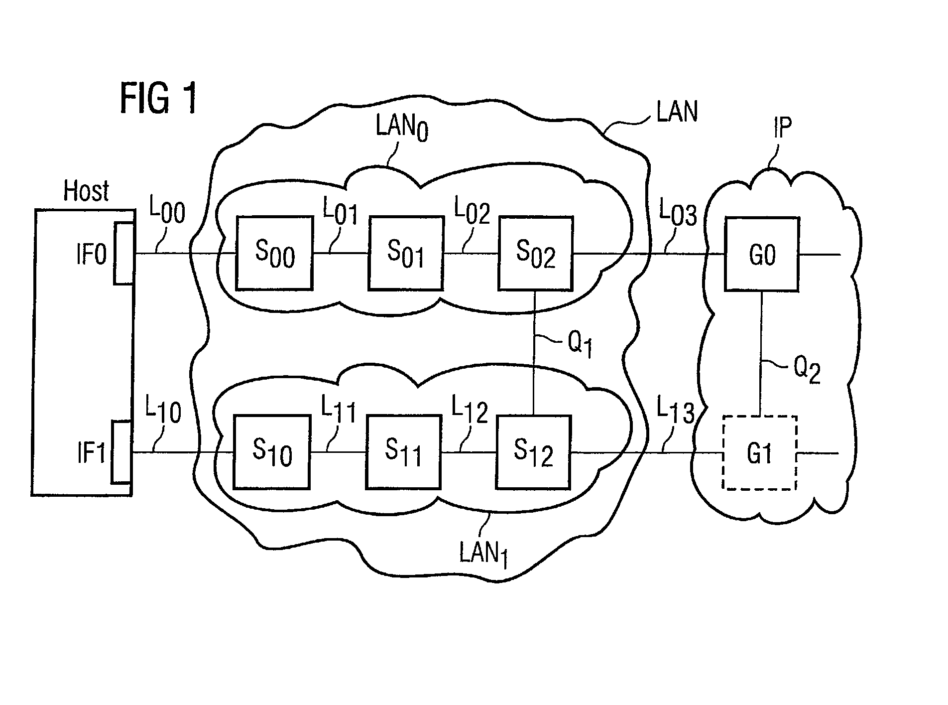
[0051] With reference to FIG. 1, the following paragraphs first describe an example of a redundant network topology for which the present invention can advantageously be used. Here, this topology serves to illustrate an exemplary embodiment of the invention, the invention being applicable to any topologies.

[0052]FIG. 1 shows a first device Host. This first device may, for example, be one of the hosts or service platforms referred to in the introductory remarks. However, the first device can be any communications device having L3 communications capabilities. For simplicity, the name Host will be used below to designate the first device.

[0053] The host is connected via a communications network N to a second device G0. This second device may, for example, be one of the gateways referred to in the introductory remarks. However, the second device can likewise be any communications device having L3 communications capabilities. For simplicity, the name Gateway will be used below to desig...


PUM


Abstract

Disclosed are test methods for testing message paths in communication networks. Also disclosed are redundant network arrangements for rerouting information when faults are detected.

Description

[0001] This application claims priority to European Application No. 02019298.5, filed Aug. 28, 2002, U.S. Provisional Application No. 60 / 406,309, filed Aug. 28, 2002, and U.S. Provisional Application No. 60 / 429,313, filed Nov. 27, 2002, the contents of which, are hereby incorporated by reference.FIELD OF THE INVENTION [0002] Disclosed are Test methods for message paths in communication networks and network elements. Also disclosed are redundant network arrangements. BACKGROUND [0003] Highly reliable communications systems often use redundant message paths to ensure that a fault affecting an individual message path does not lead to restrictions in communication. At the same time the redundancy of the message paths, i.e. for each message path there exists at least one alternate message path to which communication can be switched in the event of a fault, must be supported by the service platforms or hosts as well as by the communications system itself, i.e. by its elements, e.g. switch...

Claims


Application Information

Patent Timeline
Patent Type & Authority Applications(United States)
IPC IPC(8): G08C15/00H04L12/46H04L12/56H04L69/40
CPCH04L12/2697H04L12/4625H04L69/40H04L43/50H04L12/4633
Inventor ARNOLD, ROBERTHERTLEIN, THOMASKOPP, JORGLEITOL, STEFANSCHUMACHER, RAINERSTEMPLINGER, ROBERT
Owner SIEMENS AG
Learn More