
Overdrive digital-to-analog converter, source driver and method thereof

a digital-to-analog converter and source driver technology, applied in the field of digital-to-analog converters, can solve the problems of affecting the display quality of lcd, reducing conversion speed, increasing dac, etc., and achieves the effect of increasing the conversion speed of dac and improving the slew rate of buffer units

Inactive Publication Date: 2008-03-06
NOVATEK MICROELECTRONICS CORP
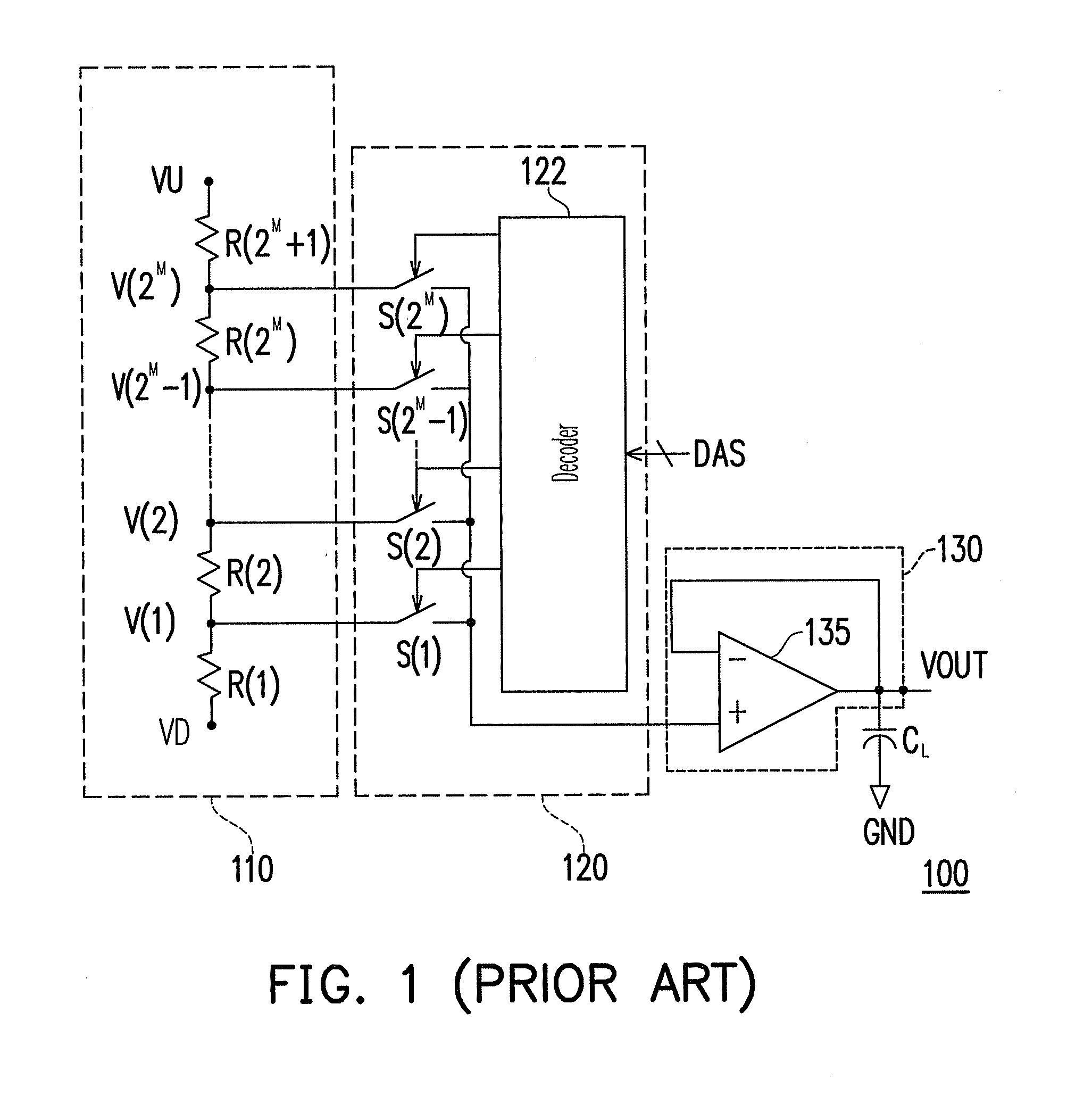
View PDF3 Cites 13 Cited by
  • Summary
  • Abstract
  • Description
  • Claims
  • Application Information

AI Technical Summary

Benefits of technology

[0010]The present invention is directed to an overdrive DAC, which compares an output voltage and a reference voltage corresponding to an input digital signal, and regulates an input voltage of a buffer unit according to a comparison result, thereby improving the slew rate of the buffer unit and increasing the conversion speed of the DAC.
[0012]The present invention is further directed to an overdrive DAC applicable to a source driver of an LCD panel. The input voltage of the buffer unit is regulated by detecting a difference between the voltages at an input terminal and an output terminal of the buffer unit, so as to improve the driving capability and the conversion speed of the source driver. Moreover, a decoder is used to select different output voltages. Thus, the number of the buffer units of the source drivers is reduced.
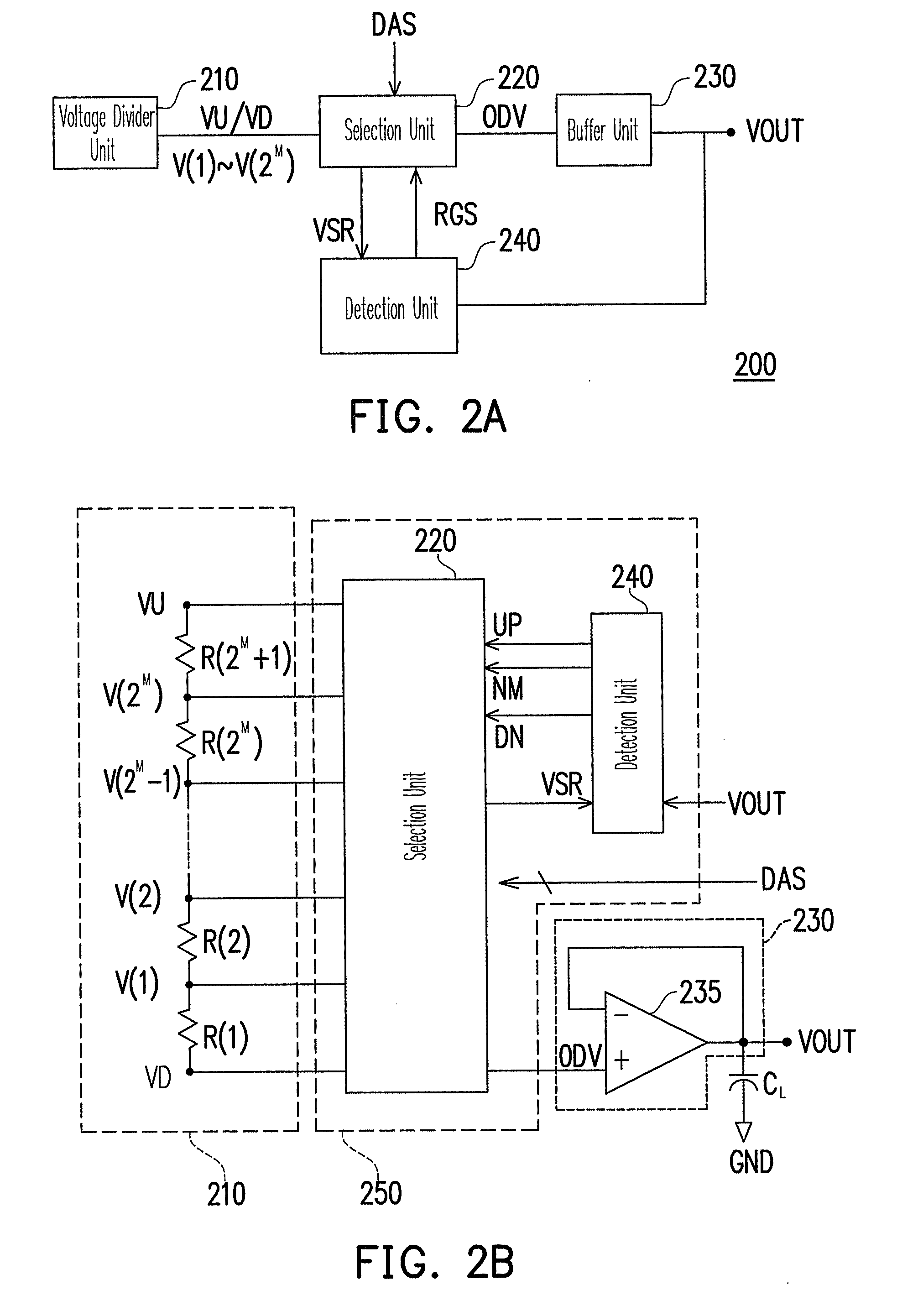
[0016]In another embodiment of the present invention, the above overdrive unit includes a selection unit and a detection unit. The selection unit is coupled to the voltage divider unit, and the selection unit has a first output terminal and a second output terminal, wherein the first output terminal is used to output the overdrive voltage and the second output terminal is used to output a specific reference voltage corresponding to the input digital signal from among the reference voltages. The detection unit is coupled to the selection unit and the buffer unit, and the detection unit compares the output voltage and the corresponding specific reference voltage to output a regulation signal to the selection unit. The selection unit regulates the overdrive voltage according to the regulation signal and the input digital signal, such that the output voltage of the corresponding buffer unit reaches the reference voltage corresponding to the input digital signal quickly.
[0019]In order to achieve the aforementioned and other objectives, the present invention provides a source driver, which includes a driving unit and a DAC. The driving unit outputs digital signals according to input display signals, and the DAC is coupled to the driving unit to generate a plurality of output voltages according to the digital signals output from the driving unit. The DAC compares the output voltages and the reference voltages corresponding to the digital signals. If the output voltages are not corresponding with the reference voltages corresponding to the digital signal, the DAC regulates the output voltages to reach the reference voltages corresponding to the digital signals quickly.
[0021]The present invention regulates the input voltage of the buffer unit in real time according to the comparison result between the output voltage and the reference voltage corresponding to the input digital signal, so as to improve the slew rate and the conversion speed of the buffer unit. Therefore, the present invention can improve the conversion speed of the DAC significantly without increasing the power consumption, and improve the display quality when the source driver drives the panel.

Problems solved by technology

Therefore, when the load on the panel end increases, the driving current required by the DAC also increases, and the conversion speed becomes lower, thus further influencing the display quality of the LCD.
Thus, the problem that the lower conversion speed of the DAC due to the load capacitor becomes more obvious, thereby further adversely influencing the display quality of the LCD.

Method used


Image

  • Overdrive digital-to-analog converter, source driver and method thereof
  • Overdrive digital-to-analog converter, source driver and method thereof
  • Overdrive digital-to-analog converter, source driver and method thereof

Examples


Embodiment Construction

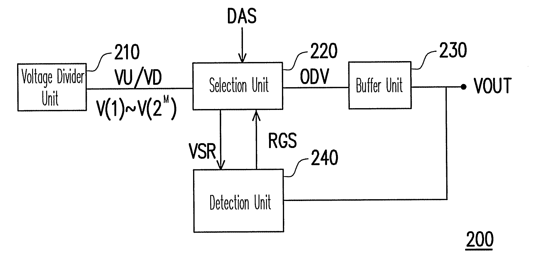
[0033]FIG. 2A is a block view of a DAC according to an embodiment of the present invention. The DAC 200 generates a corresponding analog output voltage VOUT according to an input digital signal DAS. The DAC 200 includes a voltage divider unit 210, a selection unit 220, a detection unit 240 and a buffer unit 230. The selection unit 220 is coupled to the voltage divider unit 210 and the buffer unit 230. The detection unit 240 is coupled to the selection unit 220 and the buffer unit 230.

[0034]The voltage divider unit 210 is used to provide an upper limit voltage VU, and a lower limit voltage VD, and reference voltages V(1)-V(2M) corresponding to the value of input digital signal DAS. In this embodiment, the input digital signal DAS is an M-bit signal. In other words, different input digital signals DAS correspond to different reference voltages V(1)-V(2M). The selection unit 220 provides a specific reference voltage VSR to the detection unit 240 according to the input digital signal DA...


PUM


Abstract

An overdrive digital-to-analog converter (DAC), a source driver, and a method thereof are provided. The DAC comprises a voltage divider unit, a selection unit, a buffer unit, and a detection unit. The voltage divider unit provides a plurality of reference voltages. The detection unit outputs a regulation signal according to a comparison result between a specific reference signal corresponding to an input digital signal and an output voltage output from the buffer unit. The selection unit regulates an overdrive voltage input to the buffer unit according to the regulation signal and the input digital signal. Accordingly, the output voltage of the buffer unit is changed quickly, and the conversion speed of the DAC is improved.

Description

CROSS-REFERENCE TO RELATED APPLICATION[0001]This application claims the priority benefit of Taiwan application serial no. 95131995, filed Aug. 30, 2006. All disclosure of the Taiwan application is incorporated herein by reference.BACKGROUND OF THE INVENTION[0002]1. Field of the Invention[0003]The present invention relates to a digital-to-analog converter (DAC). More particularly, the present invention relates to a DAC capable of improving conversion speed, a source driver, and a method thereof.[0004]2. Description of Related Art[0005]Conventional DACs usually adopt a decoder to output a corresponding analog voltage according to an input digital signal. A reference voltage can be generated by means of resistors connected in series. By dividing the voltage with the resistors, the reference voltage corresponding to the input digital signal can be generated. When the input digital signal changes, the decoder switches to the corresponding reference voltage, and a voltage buffer outputs a...

Claims


Application Information

Patent Timeline
IPC IPC(8): H03M1/66
CPCH03M1/765H03M1/667
Inventor YEN, CHIH-JEN
Owner NOVATEK MICROELECTRONICS CORP
Learn More