Child Locator

a locator and child technology, applied in the field of child locators, can solve the problems of not providing both locating and alert means suitable for many different types of circumstances, and is a bit expansive and unnecessary, and achieves the effect of reducing false alarms

Inactive Publication Date: 2008-03-06
HOLOYDA HANG N
View PDF12 Cites 23 Cited by
  • Summary
  • Abstract
  • Description
  • Claims
  • Application Information

AI Technical Summary

Benefits of technology

[0006]The master and monitored units may set the same or different predetermined distances at which alarms are actuated. There are two desirable aspects to this feature. In one case, the parent may want the master unit to alert when the child is, say, 50 yards away but not to actuate the monitored unit's alarm until it is, say, 75 yards away. In this case, the parent may be able to visually check the child's location or call him back before the child's alarm sounds. This would help minimize false alarms. Another desirable aspect to this feature is that the monitored unit may have a predetermined distance at which it will remind the child that he is getting too far away. However, the master unit (with the parent) is not actuated until a larger predetermined separation sequence is reached. It is also a key feature that once the monitored unit's alarm has been actuated as being too far from the master unit, it can only be deactivated by a signal sent from the master unit.
[0007]Therefore, a general object of this invention is to provide a child locator that enables a parent or guardian to monitor the location of a child and to be alerted if the child moves beyond a predetermined distance from the parent.
[0008]Another object of this invention is to provide a child locator, as aforesaid, that can determine a relative distance and direction of a monitored device and can visually display such information.

Problems solved by technology

For example, devices utilizing global position satellite technology are useful for locating an exact geographical position but are somewhat expansive and unnecessary when a child may be only a short distance away from the parent.
Although assumably effective for their intended purposes, the existing devices do not provide both locating and alert means suitable for many different types of circumstances.

Method used


Image

  • Child Locator
  • Child Locator
  • Child Locator

Examples


Embodiment Construction

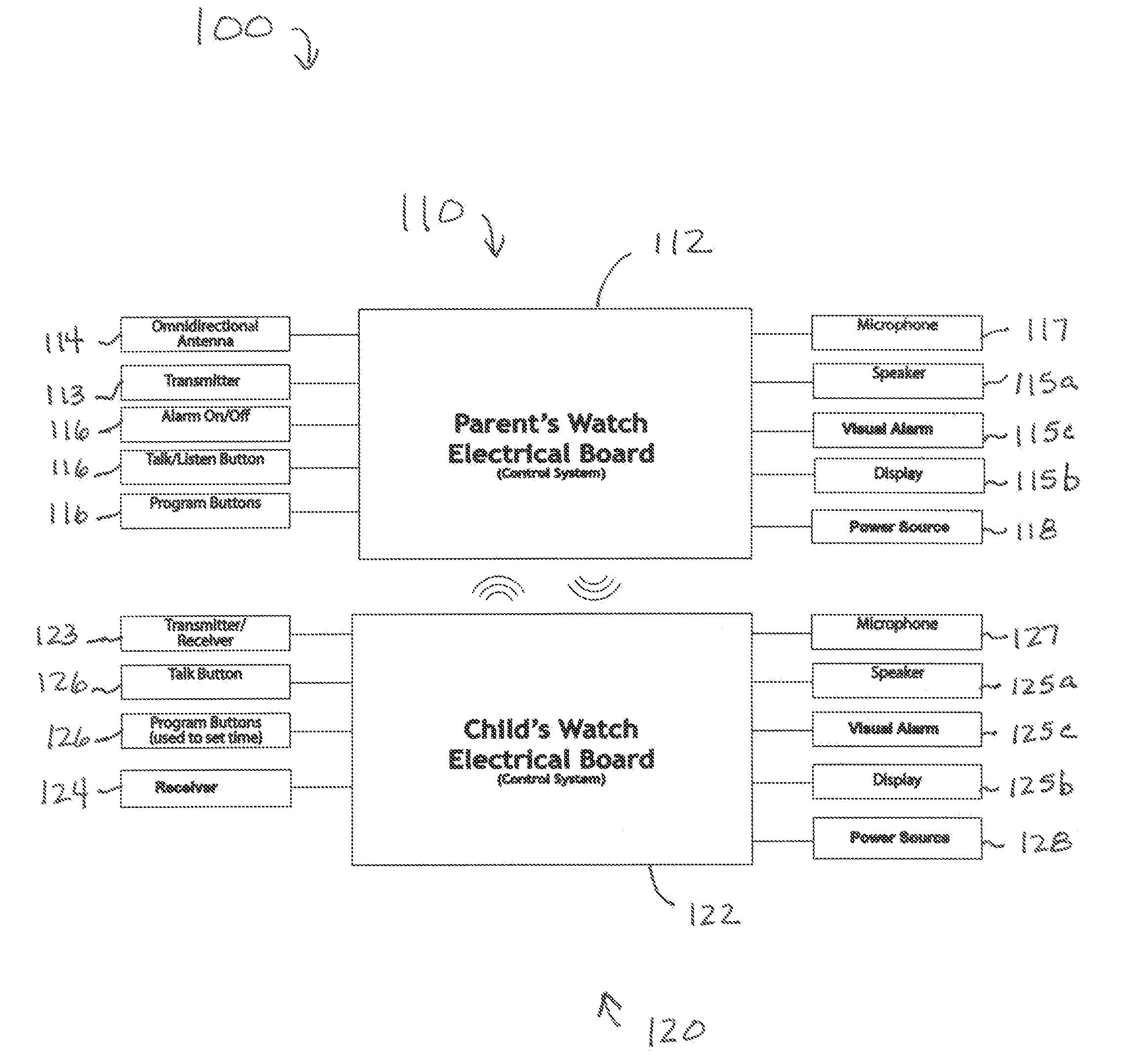
[0026]A child locator apparatus 100 according to the present invention will now be described in detail with reference to FIGS. 1a through 6 of the accompanying drawings. More particularly, a child locator apparatus 100 according to the current invention includes a master unit 110 and a monitored unit 120.

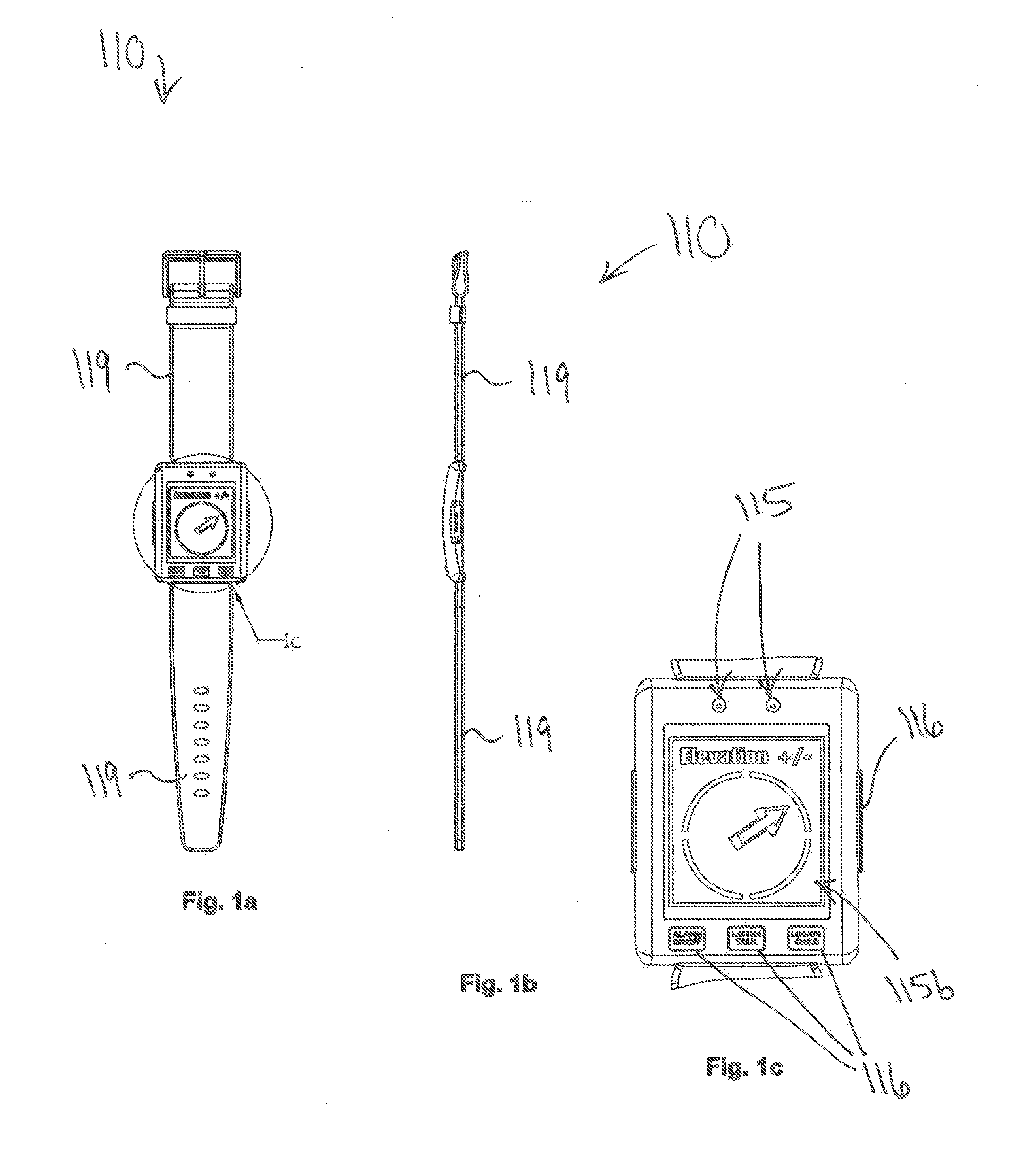
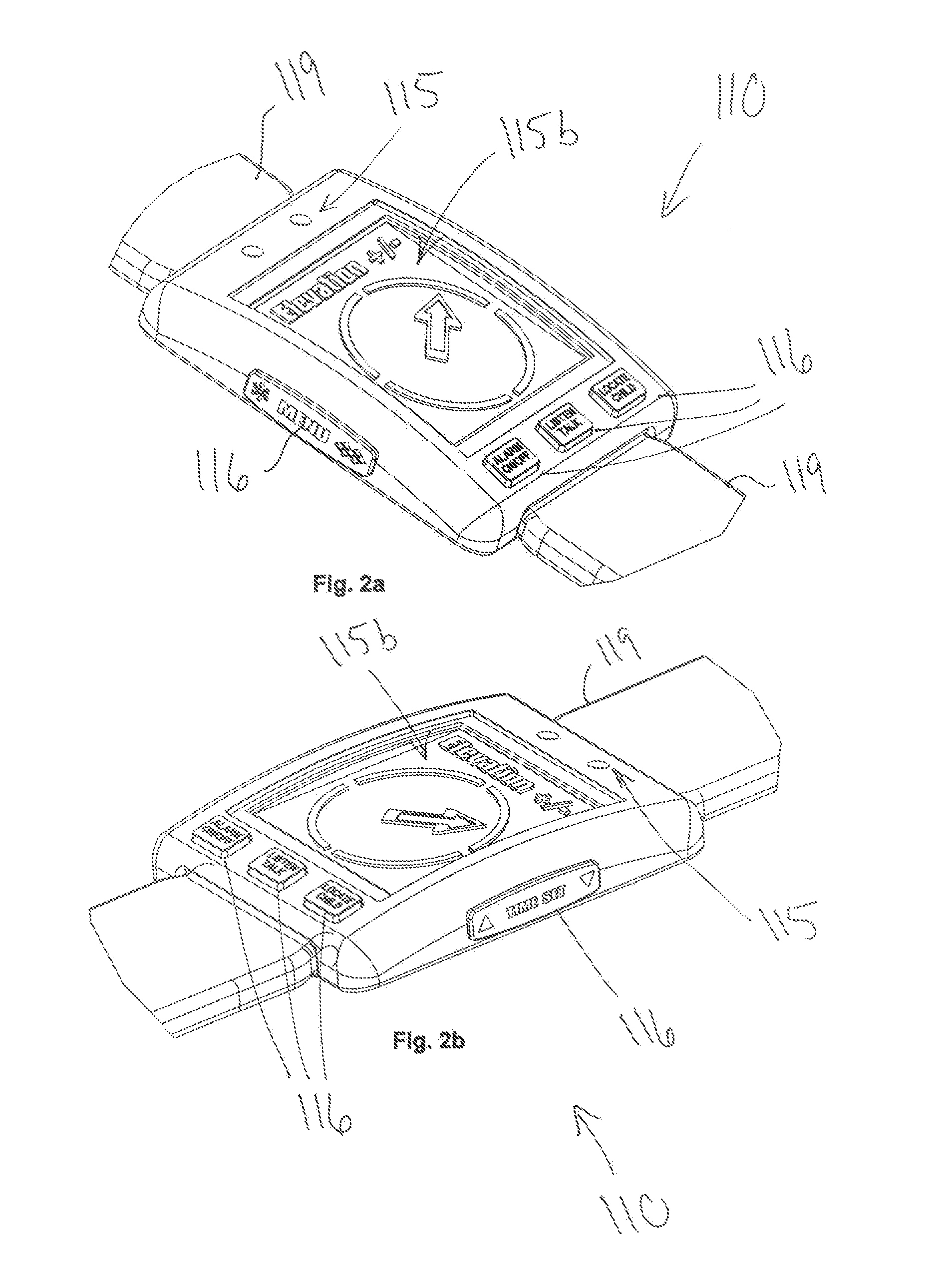
[0027]The master unit 110 (shown in FIGS. 1a through 2b and FIG. 5) may have a processor 112 (also referred to as a master processor) in electrical communication with a transmitter 113 (also referred to as a master transmitter), a receiver 114 (also referred to as a master receiver), an alarm 115 (also referred to as a master alarm), an input device 116 (also referred to as a master input device), a microphone 117 (also referred to as a master microphone), and / or a power source 118 (also referred to as a master power source). The master alarm 115 may include, for example, a speaker 115a (also referred to as a master speaker), a display 115b (also referred to as a master display), an...


PUM


Abstract

A child locator that enables a parent to locate a child includes a master unit for wear by a parent and a monitored unit for wear by a child. The master unit may actuate an on-board alarm when its processor determines that the monitored unit is beyond a first predetermined distance and may actuate an alarm on the monitored unit when the separation distance is beyond another distance. The first and second predetermined distances may be the same of different. The child locator may also actuate the monitored unit manually and the alarms may be audible or visual. Once an alarm on the monitored unit is activated, a signal from the master unit is required to deactivate it. The master unit may include a directional antenna for determining a position on the monitored unit. The monitored unit may deliver voice data to a speaker at the monitored unit.

Description

BACKGROUND OF THE INVENTION[0001]This invention relates generally to child tracking or locating devices and, more particularly, to a child locator that enables an adult to locate a monitored device, to actuate an alarm at the monitored device automatically if a predetermined separation distance is reached or manually as desired, or to communicate with the monitored device.[0002]Parents and children are frequently in environments or situations where they may become separated. This separation may be inadvertent, such as straying away at a shopping mall, or voluntary, such as playing at a park or beach. In either case, a parent or guardian often desires to locate the child very quickly to verify the child's safety. Depending on the situation, an audible alarm worn by the child may be desired while other time, say at the beach at night, a bright visual alarm might be more desirable. Of course, it would be desirable to just be able to hear the child playing without activating an audible ...

Claims


Application Information

Patent Timeline
IPC IPC(8): H04Q7/00G08B1/08G08B23/00
CPCG08B21/0202
Inventor HOLOYDA, HANG N.
Owner HOLOYDA HANG N
Why Eureka
Try Eureka