
Maintainable Dynamic Instrumentation Technique For Changing Versions Of Software

a dynamic instrumentation and software technology, applied in the direction of instruments, error detection/correction, computing, etc., can solve the problems of not being able to adjust the location of local variables and arguments, not having flexibility, and not having the same execution environment for the probe handler

Inactive Publication Date: 2008-02-28
IBM CORP
View PDF14 Cites 32 Cited by
  • Summary
  • Abstract
  • Description
  • Claims
  • Application Information

AI Technical Summary

Benefits of technology

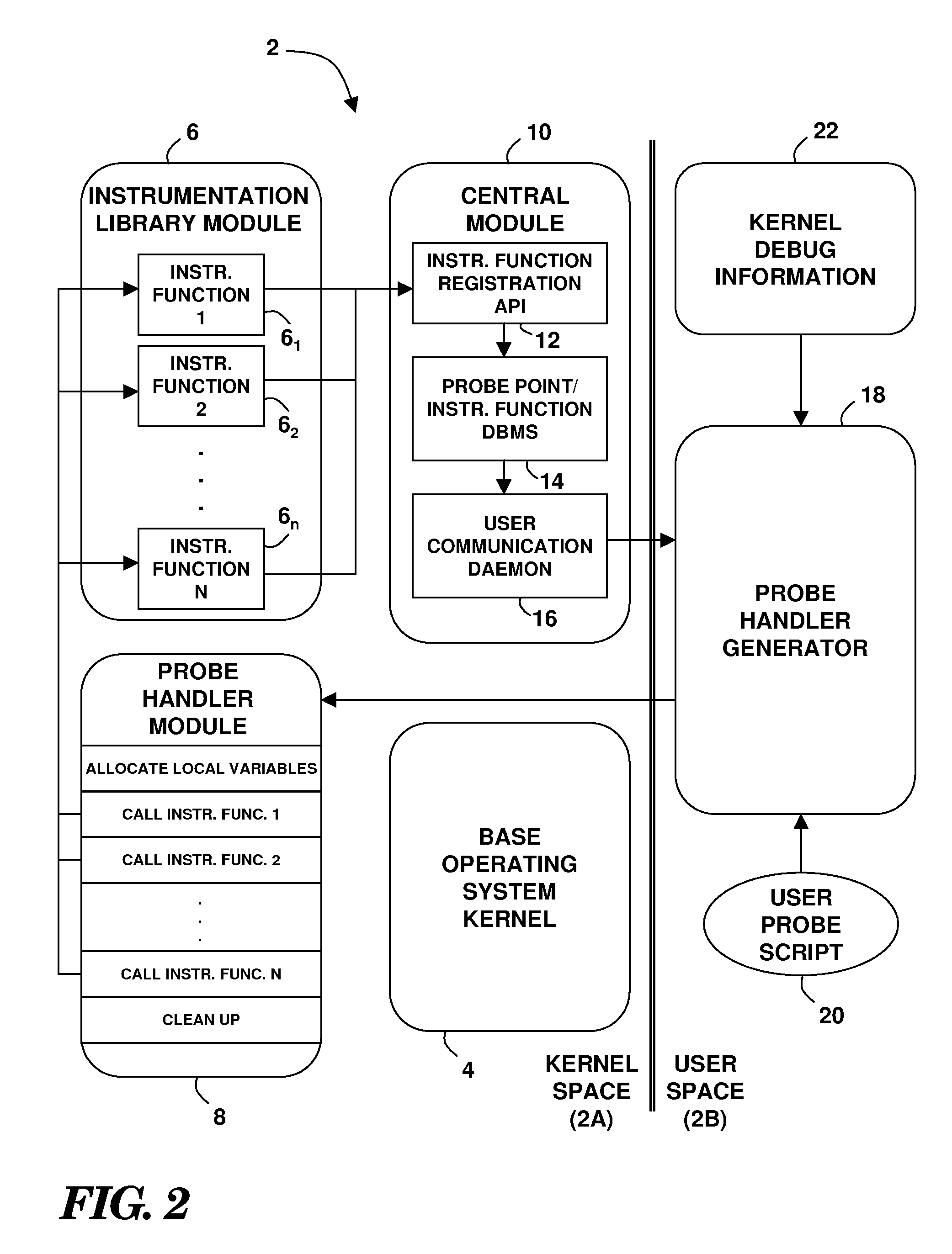
[0007]The foregoing problems are solved and an advance in the art is obtained by a novel method, system and computer program product for the dynamic instrumentation of a running software system. One or more callable instrumentation functions are accessible in a first memory space associated with the software system. The one or more callable instrumentation functions are adapted to probe an operation of the software system and return data regarding the probed operation. Probed operation environment information needed by the one or more instrumentation functions is provided to a second memory space associated with the software system. First memory space addresses associated with the probed operation environment information are determined from a resource that is accessible in the second memory space. A probe handler is generated that includes calls to the one or more instrumentation functions with references to the first memory space addresses. The probe handler is callable as part of the probed operation.

Problems solved by technology

This is in contrast to statically instrumenting the system when it is created, which offers no flexibility.
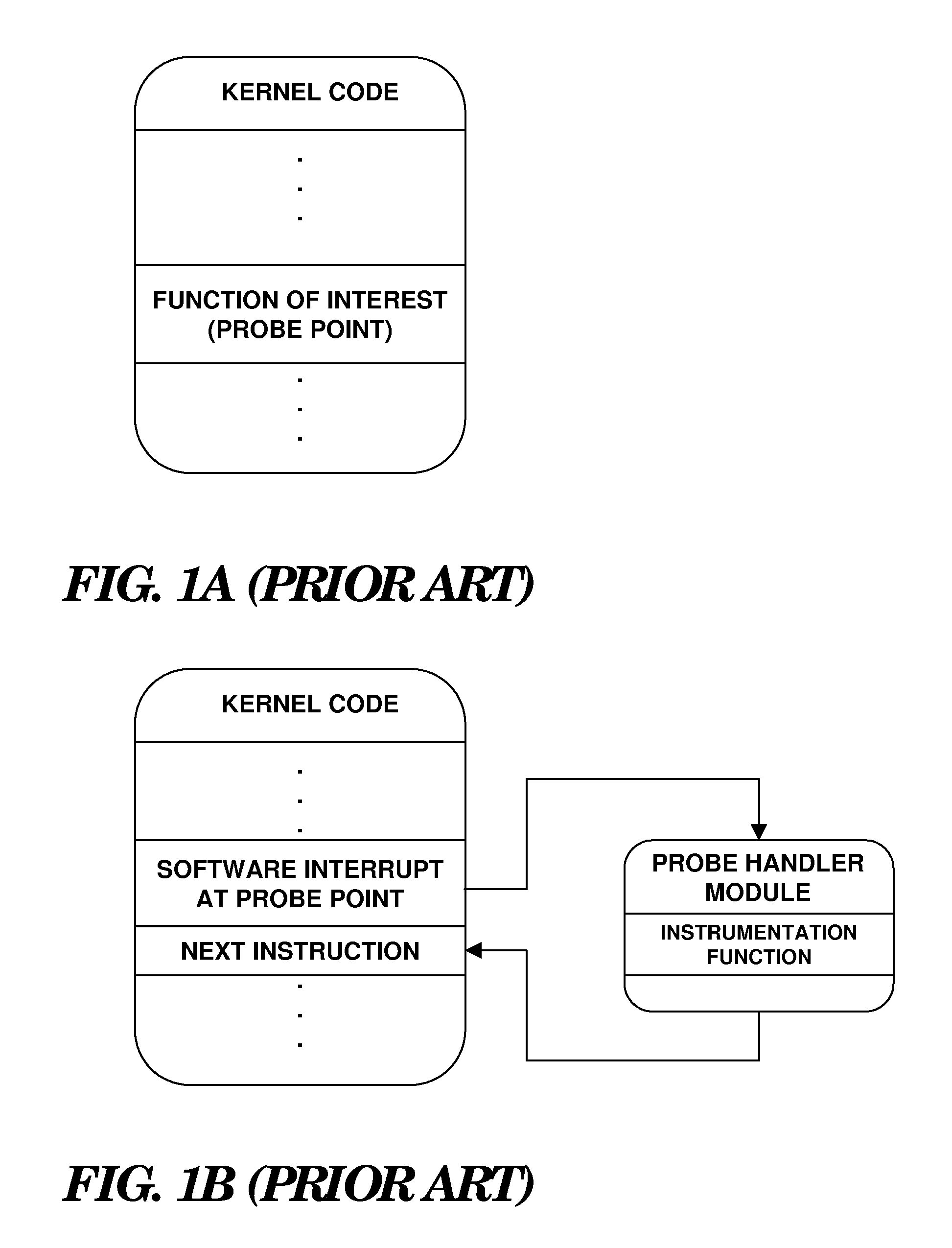
One problem with conventional instrumentation solutions is that the probe handler needs the same execution environment as that of the function being interrrupted, including access to local variables and arguments.
Unfortunately, the location of local variables and arguments is not fixed, and depends on various parameters such as the compiler version used to compile the operating system, and the compile options and hardware platform type specified during compilation.
For this reason, local variables and arguments can not be easily accessed in the probe handler without consulting additional debug information.
It is not desirable to access debug information from a probe handler insofar as this information is generally not readily available to the operating system.
Due to this problem, it is not easy to write dynamic instrumentation code in a portable form.
It will be appreciated that this method is not desirable insofar as it is not practical or economical to write such code.

Method used


Image

  • Maintainable Dynamic Instrumentation Technique For Changing Versions Of Software
  • Maintainable Dynamic Instrumentation Technique For Changing Versions Of Software
  • Maintainable Dynamic Instrumentation Technique For Changing Versions Of Software

Examples


Embodiment Construction

[0019]Turning now to the Drawing figures wherein like reference numerals indicate like components in all of the several views, FIG. 2 illustrates an exemplary dynamic instrumentation system 2. Although the instrumentation system 2 may be variously implemented in software, firmware, hardware, or any combination thereof, the following discussion is based on an exemplary embodiment wherein the instrumentation system 2 comprises software program logic that is capable of execution on commodity data processing systems, including personal computers, workstations, as well as more complex hardware such as midrange and mainframe computers. According to this exemplary software implementation, the software logic of the instrumentation system 2 may collectively reside in a first memory space 2A (shown on the left-hand side of FIG. 2) and a second memory space 2B (shown on the right-hand side of FIG. 2), so as to be available for execution on a central processing unit (CPU) (see discussion of FIG...


PUM


Abstract

A technique for the dynamic instrumentation of a running software system. One or more callable instrumentation functions are accessible in a first memory space associated with the software system. The one or more callable instrumentation functions are adapted to probe an operation of the software system and return data regarding the probed operation. Probed operation environment information needed by the one or more instrumentation functions is provided to a second memory space associated with the software system. First memory space addresses associated with the probed operation environment information are determined from a resource that is accessible in the second memory space. A probe handler is generated that includes calls to the one or more instrumentation functions with references to the first memory space addresses. The probe handler is callable as part of the probed operation.

Description

BACKGROUND OF THE INVENTION[0001]1. Field of the Invention[0002]The present invention relates to diagnostic tools for analyzing software. More particularly, the invention is directed to the dynamic instrumentation of running software in order to gather runtime data as the software executes. Still more particularly, the invention concerns a technique for implementing a portable dynamic instrumentation tool that accommodates variations in execution environment that arise from differences in compiler versions, compile options, hardware platform particulars and other parameters.[0003]2. Description of the Prior Art[0004]By way of background, in order to analyze the operation of a complex system such as a large software program, it is important to be able to gather operational information while the system is running, without halting execution, modifying the system, and then restarting it. One approach is to dynamically add instrumentation code to the running system when data is needed, s...

Claims


Application Information

Patent Timeline
Patent Type & Authority Applications(United States)
IPC IPC(8): G06F9/45G06F9/44
CPCG06F11/3644
Inventor PRADADARAO, AKULAVENKATAVARA
Owner IBM CORP
Learn More