
Non-Surgically Correcting Abnormal Knee Loading: Treatment and Training Equipment

a knee loading and non-surgical technology, applied in the field of training and treatment equipment, can solve problems such as limiting the range of motion of the leg, and achieve the effects of restoring the range of motion and muscle strength of the knee, correcting the rotational malalignment, and restoring muscle function

Inactive Publication Date: 2008-02-28
RGT UNIV OF COLORADO THE BODY
View PDF37 Cites 18 Cited by
  • Summary
  • Abstract
  • Description
  • Claims
  • Application Information

AI Technical Summary

Benefits of technology

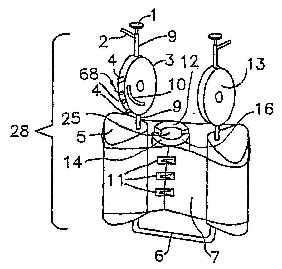
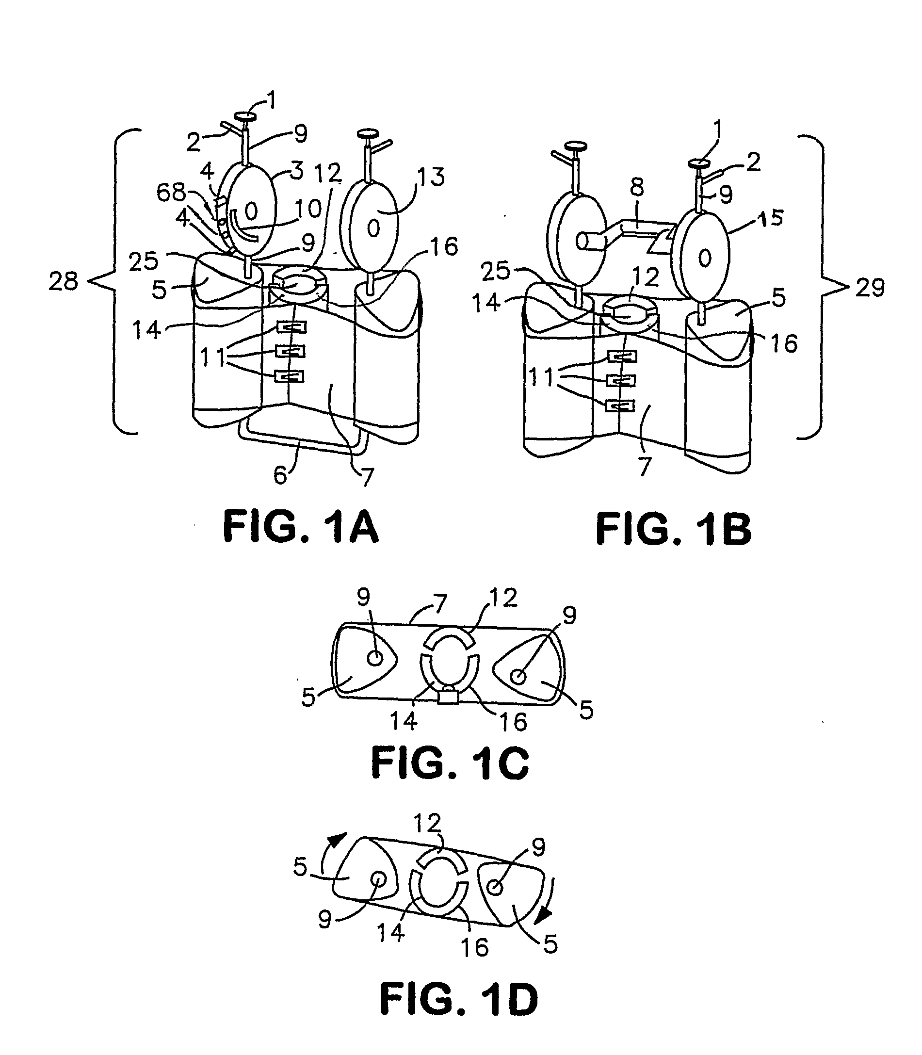
[0006]The present invention helps patients restore the rotational alignment of the malaligned knee to that of a healthy knee, and restore the knee function by regaining the range of motion and strengthening of the knee muscles. Therefore, it can ultimately correct the deformity to the extent allowed by the underlying articular cartilage structural damage. Accordingly, the present invention provides a method of leg exercise that can help treat knee osteoarthritis by simultaneously correcting the knee rotational malalignment and restoring the knee function, which allows for an optimal loading distribution across the knee joint and ultimately minimizes cartilage degeneration.
[0009]In a further embodiment, one or both range limiters can include a range limiter track through which an immovable range limiter bar can extend, thereby constraining the range of leg flexion and / or extension during exercise. The flexion / extension range can be further controlled by range limiter pins positioned at variable locations within a range limiter track. In one embodiment, a plurality of passages can extend through the range limiter so that a range limiter pin placed within one or more of the plurality of passages can obstruct the range limiter track, thereby limiting the leg's range of motion. The range limiter track can be any portion of a notional circle centered on the center of rotation of the range limiter assembly. Preferably, the portion can be between 110° to 130° of a notional circle, more preferably approximately 120°, wherein approximately 120° can be between 115° to 125°. A series of equally spaced pin receiving passages within a 1200 range limiter track can control extension / flexion in 5° increments. Thus, by varying the number of passages to the range limiter track, the incremental control can be varied.
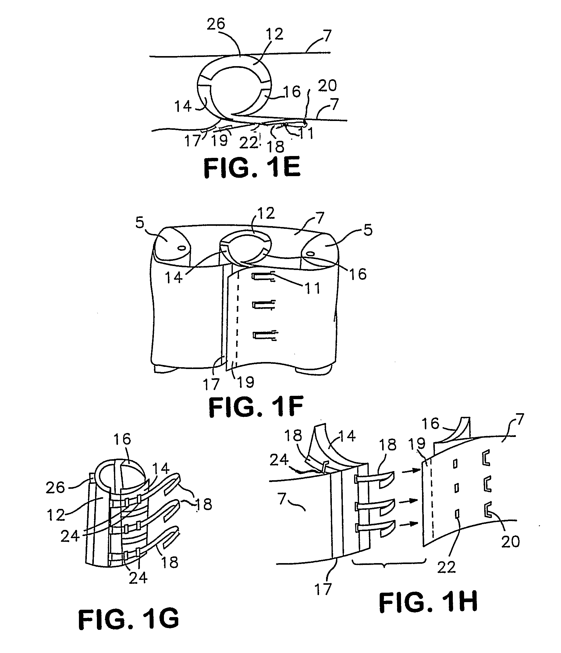
[0011]A further embodiment of the invention can be a cuff that can include a calf pad, a left shin pad, and a right shin pad. The right shin pad can comprise a plurality of pads wherein each of the plurality of pads can be positioned at a different vertical distance from the knee joint. In a preferred embodiment the right shin pad comprises three such pads. The left and right shin pads can be connected to opposite ends of the calf pad by an elastic material to provide support as the user inserts a lower leg into the cuff. Each pad can also be connected to the sheet so that rotation of the rotational drums can generate a rotational, as well as compressive, forces on the tibia secured by the cuff.
[0012]To assist in generating forces suitably positioned on the tibia, a series of straps, with at least one strap for each pad of the right shin pad, can be connected to the end of the calf pad to which the right shin pad is connected. Strap guides can be connected to the plurality of right shin pads to guide the straps from the calf pad, along the outward-facing side the right shin pad, and through the sheet. The straps can traverse through the sheet by a series of straps holes in a region of the sheet to which the left shin pad can be connected. These straps can be tightened to secure the cuff around the tibial portion of the lower leg to reduce or eliminate slippage between the cuff and leg. The sheet can be discontinuous between the right and left shin pad-connecting region to facilitate cuff tightening by the belts for various sized legs.
[0015]Resistance means can be generated as known in the art and can include elastics, springs, hydraulics or a brake. In one embodiment, a rubber brake attached to one end of the resistance adjustment pin can contact the vertical bar inside the range limiter disk so that tightening the pin can increase the friction between the vertical bar and the rubber brake, thereby increasing the force required to rotate the lower leg. The resistance adjustment pin can be connected to the free end of the vertical bar so that adjusting the pin increases the resistance between the resistance means and the vertical bar. Alternatively, one end of the resistance adjustment pin can be positioned on the outside of the range limiter, with a portion of the pin traversing a passage through the range limiter so that a rubber brake connected to the pin's other end can contact the vertical bar within the range limiter. Tightening the resistance adjustment pin can increase the rotational resistance; loosening the resistance adjustment pin can decrease or eliminate the rotational resistance.
[0018]The invention used in concert with weight training exercise equipment can: (1) allow the knee to regain normal rotational range of motion and correct the rotational malalignment of the knee, (2) allow the knee to regain the muscle function of rotational control, (3) restore the range of motion and muscle strength of the knee, and (4) correct three-dimensional knee malalignment. The invention can be utilized by the younger population, including athletes as well as others, to correct rotational malalignment and can be used in physical therapy clinics, athletic training facilities as well as fitness centers.

Problems solved by technology

In one embodiment, a plurality of passages can extend through the range limiter so that a range limiter pin placed within one or more of the plurality of passages can obstruct the range limiter track, thereby limiting the leg's range of motion.

Method used


Image

  • Non-Surgically Correcting Abnormal Knee Loading: Treatment and Training Equipment
  • Non-Surgically Correcting Abnormal Knee Loading: Treatment and Training Equipment
  • Non-Surgically Correcting Abnormal Knee Loading: Treatment and Training Equipment

Examples


Embodiment Construction

[0028]The invention may be further understood by the following non-limiting examples. Although the description herein contains many specificities, these should not be construed as limiting the scope of the invention but as merely providing illustrations of some of the presently preferred embodiments of the invention. For example, thus the scope of the invention should be determined by the appended claims and their equivalents, rather than by the examples given. All references cited herein are hereby incorporated by reference to the extent not inconsistent with the disclosure hereof.

[0029]The present invention can be used to treat a variety of knee pathologies involving rotational malalignment of the knee joint, including osteoarthritis, traumatic injury, meniscal injury, articular cartilage and ligament injury as well as abnormalities arising from rheumatoid arthritis. “Rotational alignment” is used to describe the amount the tibia is circumferentially rotated compared to the femur....


PUM


Abstract

The invention provides a device and a method for exercising a user's leg whose lower leg tibial portion can be rotatably controlled during exercise. The device includes user-controlled rotatable drums connected to a sheet that surrounds a lower leg cuff for rotating and providing corrective forces on a user's knee joint during leg exercise. The device can be used with weight training equipment commonly found in commercial gyms, as well as in a user's home, or in clinics, to assist in rehabilitating malaligned knee joints.

Description

FIELD OF INVENTION[0001]This invention is in the field of training and treatment equipment, and methods to reduce and correct abnormal knee loading using this equipment.BACKGROUND OF THE INVENTION[0002]The knee is composed of three bones, the patella (knee cap), the femur and the tibia. The meniscus (cartilage), composed of the lateral and medial menisci, cushion and distribute the weight of the femur uniformly across the joint. The gaps between the tibia and femur on the inside and outside of the knee are called the “medial” and “lateral” compartments, respectively. The condyle is the smooth, rounded end of the femur that allows the femur to move easily over the surface of the menisci on the tibial plateau. The ligaments and tendons control the motion of the knee joint. The tendons connect the patella; the ACL (anterior cruciate ligament) and PCL (posterior cruciate ligament) prevent the tibia from sliding forward or backward and limit the tibia's rotation; the collateral ligaments...

Claims


Application Information

Patent Timeline
Patent Type & Authority Applications(United States)
IPC IPC(8): A61F5/00
CPCA61H1/024A61H2205/102A61H2205/106A63B21/062A63B21/1403A63B21/1423A63B23/0494A63B2023/003A61H2201/1253A61H2201/1623A61H2201/1633A61H2201/164A61H2201/1642A61H2201/1671A61H2203/0431A63B21/0628A63B21/4001A63B21/4011
Inventor GAMADA, KAZUYOSHI
Owner RGT UNIV OF COLORADO THE BODY
Learn More