Electrical connector with improved latching structure

a technology of latching structure and electric connector, which is applied in the direction of electrical apparatus, connection, coupling device connection, etc., can solve the problems of difficulty in manufacture, insufficient biasing force to secure the connector modules, and unreliable lever fixing on the retainer member, etc., and achieve the effect of effective latching structur

Inactive Publication Date: 2008-02-28
HON HAI PRECISION IND CO LTD
View PDF10 Cites 4 Cited by
  • Summary
  • Abstract
  • Description
  • Claims
  • Application Information

AI Technical Summary

Benefits of technology

[0008]It is therefore a general object of the present invention to provide an effective latching structure providing enough biasing force to ensure a firmly connection between mated complementary connectors.
[0009]It is another object of the present invention to provide an effective latching structure with simple configuration and easily to manufacture.

Problems solved by technology

However, the biasing force is insufficient to secure the connector modules to the mating connector.
Moreover, it is unreliable that the lever is fixed on the retainer member by a clip.
Further, the complex latching assembly adds difficulties to manufacture and increases the product cost correspondingly.

Method used


Image

  • Electrical connector with improved latching structure
  • Electrical connector with improved latching structure
  • Electrical connector with improved latching structure

Examples


Embodiment Construction

[0019]Reference will now be made in detail to the preferred embodiment of the present invention.

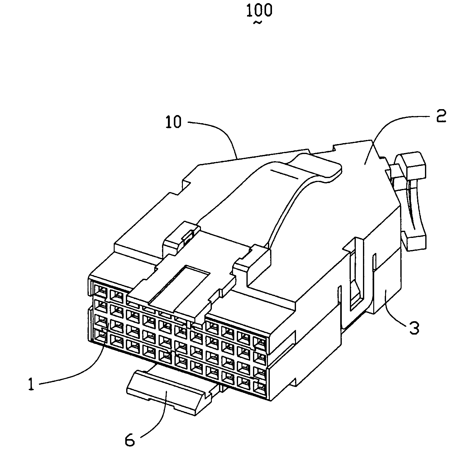
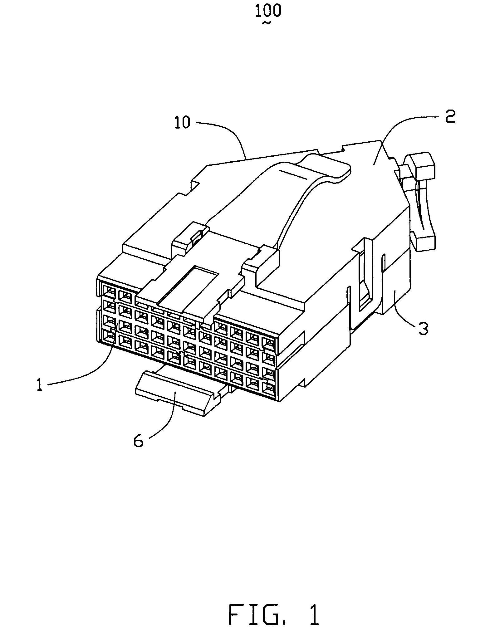
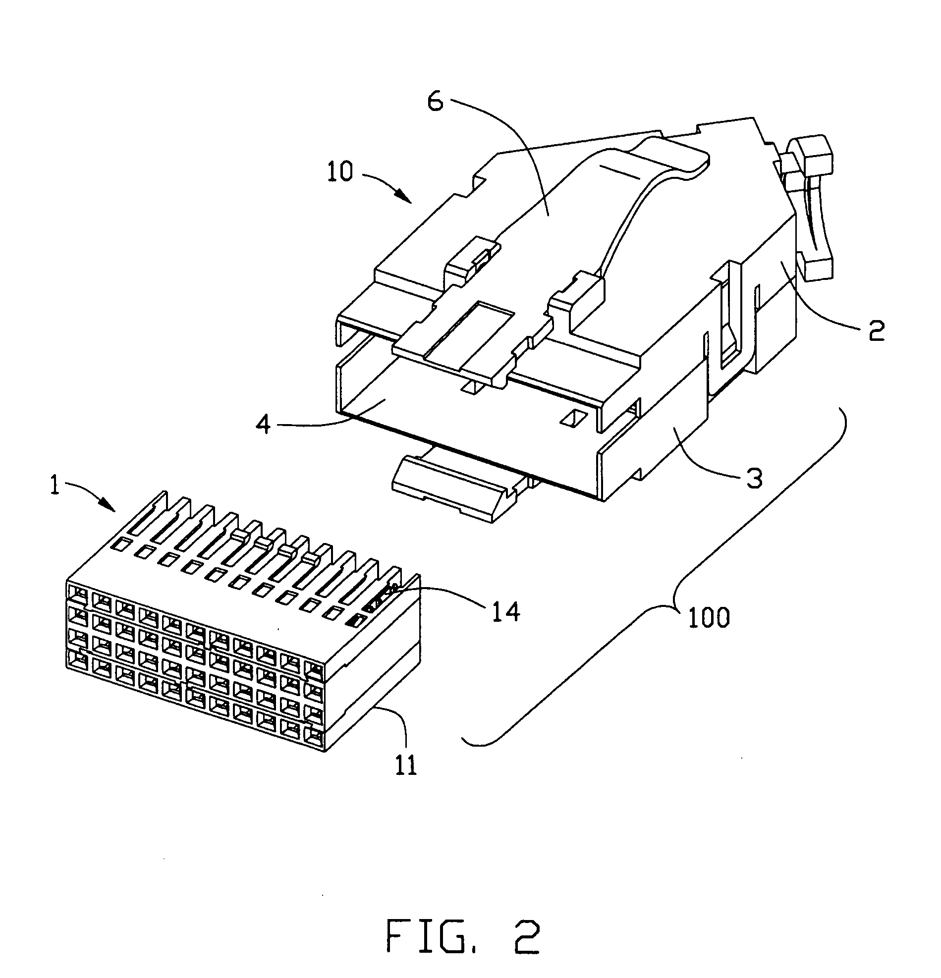
[0020]As shown in FIG. 1 and FIG. 2, an electrical connector 100 in accordance with the present invention is typically terminated with a plurality of wires or cables (not shown) and mates with a backplane connector mounted on a printed circuit board (not shown). The electrical connector 100 includes a plurality of electrical connector modules 11 assembled together as a connector block 1 for engaging with the complementary backplane connector. In the preferred embodiment, the connector block 1 includes two opposite “side modules” and one “central module” sandwiched between the two “side modules”. Each side module 11 has one row of insulated contacts 14 (only one illustrating contact is shown) each electrically connecting to a corresponding wire. The electrical connector 100 forms a housing or a cover 10. The housing 10 has a first housing member 2 and a second housing member 3 which mate w...


PUM


Abstract

An electrical connector (100) includes a housing (10) for receiving a number of connector modules (11), and a latching member (6) rotatably mounting on the housing (10). The latching member (6) includes an intermediate portion (61) defining a pivotable portion therewith and an engagement portion (62) extends from the intermediate portion (61) for engaging to a complementary connector. The latching member (6) also includes an arc-shaped actuating portion (63) extending from the intermediate portion (61) opposite to the engagement portion (62) and provides biasing force by itself inflection.

Description

BACKGROUND OF THE INVENTION[0001]1. Field of the Invention[0002]The present invention relates generally to an electrical connector, and particularly to a latching structure securing the connection between the electrical connector and a mated complementary connector.[0003]2. Description of Prior Art[0004]Backplane connectors are generally mounted on printed circuit boards used in high-speed and high-density communication system. Cable connectors are often provided to mate with the backplane connectors. It is common to employ a latching member to secure the connection between the backplane connector and the cable connector.[0005]One such latching assembly is disclosed in U.S. Pat. No. 6,371,788, issued on Apr. 16, 2002. In this patent, a latching assembly for securing a plurality of connector modules to a mating connector in mating engagement includes a retainer member that engages and holds the plurality of connector modules together as a block. A latching lever is movably mounted to...

Claims


Application Information

Patent Timeline
Patent Type & Authority Applications(United States)
IPC IPC(8): H01R13/627
CPCH01R13/6275
Inventor JOHNSON, LEWIS R.HSU, CHUN-HSIUNG
Owner HON HAI PRECISION IND CO LTD
Why Eureka
Try Eureka