Networked appliance information display apparatus and network incorporating same

a technology of information display and networked appliances, applied in the field of network information management and control, can solve the problems of not being able to add such a user interface display to many of these appliances, not being able to achieve the effect of easy entry of daily thermostat programming events, and not being able to use less effective troubleshooting methods

Inactive Publication Date: 2008-02-28
RANCO OF DELAWARE
View PDF20 Cites 245 Cited by
  • Summary
  • Abstract
  • Description
  • Claims
  • Application Information

AI Technical Summary

Problems solved by technology

However, traditional home appliances, such as water heaters, pool pumps, and the like, even when capable of communicating the information related to their operation, lack an external user interface display that is easy to read and readily accessible to the user.
Adding such a user interface display to many of these appliances is not cost effective.
Hence, while some home appliances are able to relay this information to service technicians, most consumers do not have the equipment necessary to retrieve this information from the appliance, and therefore must resort to less effective troubleshooting methods or call the service technician.
Furthermore, many such devices are responsible for running the day-to-day operation of an average home, and therefore have a direct impact on a consumer's energy costs.
However, most home appliances are not networked and monitoring of device status and programming schedules throughout the home requires the consumer to separately interface with each device.
Thus, not having a centralized display of the desired home status information, leads to difficulty in coordinating the operation of devices operating in different programming modes.
Finally, while such home appliances as a thermostat, have traditionally been used to relay the status and programming information related to the connected heating, ventilation, and air conditioning (HVAC) equipment, a traditional thermostat user interface is not intuitive to the user.

Method used


Image

  • Networked appliance information display apparatus and network incorporating same
  • Networked appliance information display apparatus and network incorporating same
  • Networked appliance information display apparatus and network incorporating same

Examples


Embodiment Construction

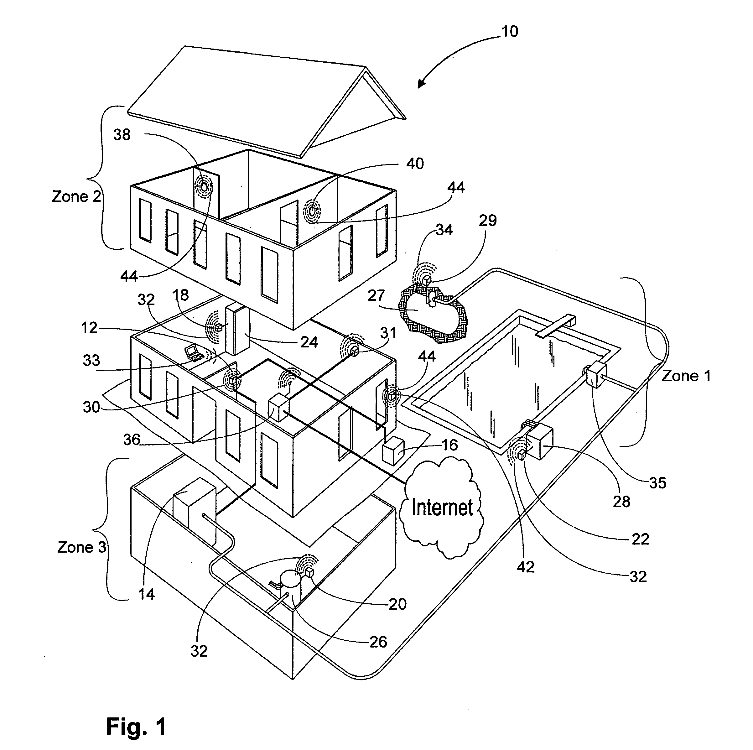
[0033]FIG. 1 depicts an exemplary environment of a system according to the present invention showing a network of nodes, with at least one local sensor node monitoring a building 10 while in communication with one or more remote nodes, or devices, located in or proximate to the building 10. The local sensor node, which preferably is a thermostat 12, acts as a hub for sensing and controlling the ambient temperature, as well as for managing the programming and status information related to the thermostat 12 and to the connected devices. Although in FIG. 1 the system of the present invention is depicted in a home environment, one skilled in the art will recognize that the present invention is not limited to a home environment, but may also be installed in other environments, such as in a commercial environment, for example.

[0034]In this embodiment, the thermostat 12 connects to the furnace 14 and the air conditioning unit 16 in a conventional manner, while other embodiments include wir...


PUM


Abstract

The graphic user interface of an HVAC thermostat displays the programming and status information for remote devices in communication with the thermostat, such as various home sensors and appliances. In an embodiment, the thermostat includes a touch screen display to present the user with a plurality of user interface screens. The monthly calendar interface screen includes a calendar graphic area comprising a matrix display of dates for a full month. The user selects a programming interval for which to enter the thermostat programming events from the calendar graphic area. The user interface includes a clock face interface screen for entry of thermostat programming events. The clock face screen includes a pair of clock face graphic areas for each daily thermostat programming event. The user interface also includes a screen for displaying the programming and status information for remote devices selected from a list of devices in communication with the thermostat.

Description

CROSS-REFERENCE TO RELATED APPLICATIONS[0001]This patent application is related to a copending U.S. patent application Ser. No. 11 / 031,087, filed Jan. 6, 2005, which is herein incorporated by reference in its entirety for everything it describes and teaches.FIELD OF THE INVENTION[0002]The present invention relates generally to network information management and control, and more particularly to centralized display of information related to networked home appliances and other devices.BACKGROUND OF THE INVENTION[0003]With a growing sophistication of consumer electronics, there is an increasing number of home electronic devices capable of programmable operation and status reporting. When it comes to home appliances, an average consumer has come to expect a certain level of intelligence built into each appliance, such as electronic timers, temperature readouts, and battery status displays.[0004]However, traditional home appliances, such as water heaters, pool pumps, and the like, even w...

Claims


Application Information

Patent Timeline
Patent Type & Authority Applications(United States)
IPC IPC(8): B64D13/00F24D19/10G05D23/00F25B49/00G01M1/38
CPCF24F11/0012G05D23/1904F24F2011/0068F24F11/30F24F2110/10F24F11/56F24F11/523F24F11/58F24F11/46G05D23/1934
Inventor WAGNER, PHILLIP RYANCHAPMAN, JOHN GILMANRAO, JOSEPH P.ASHWORTH, NICHOLASCATLIN, GEORGE NORMANBURT, ROBERT
Owner RANCO OF DELAWARE
Why Eureka
Try Eureka