
Injection molded multiple layer glazings

Active Publication Date: 2008-02-28
SOLUTIA INC
View PDF26 Cites 19 Cited by
  • Summary
  • Abstract
  • Description
  • Claims
  • Application Information

AI Technical Summary

Benefits of technology

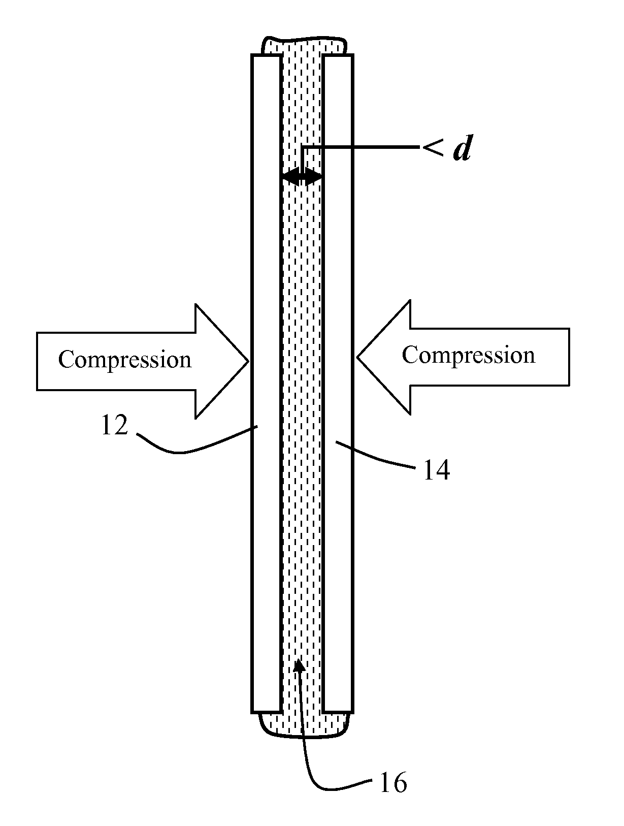
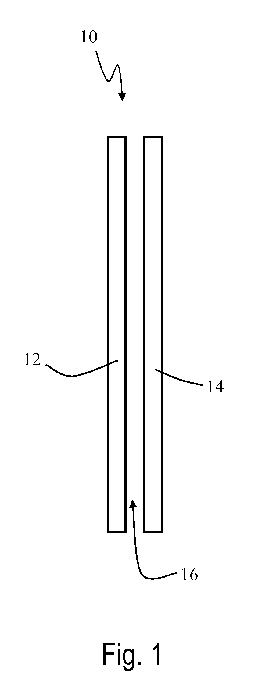
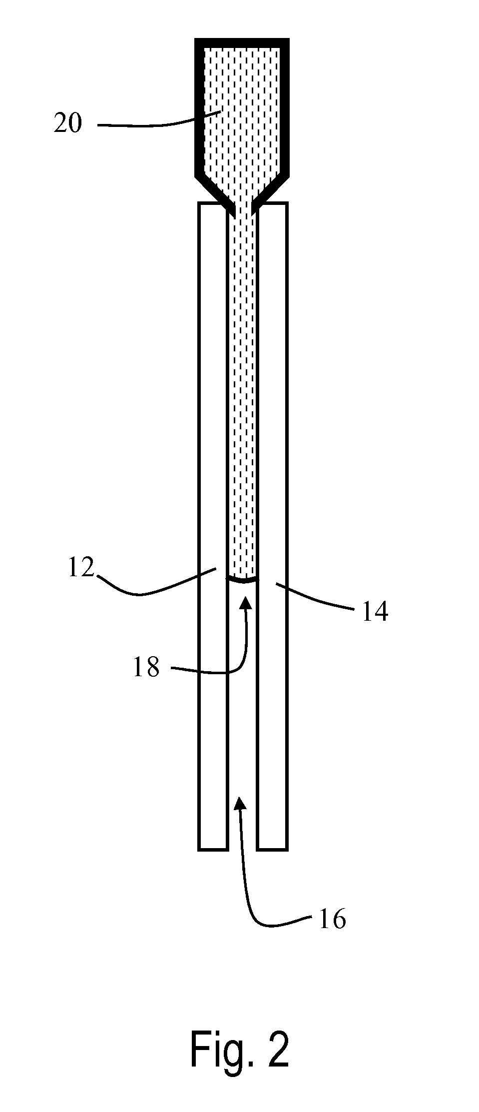
[0009]The present invention is directed to the use of injection molding to form polymeric interlayers directly between two rigid substrates that are positioned so that after injection of the melted polymeric material and after cooling, the resulting multiple layer panel functions as a safety panel that can be used in any appropriate conventional safety glazing application. Methods of the present invention utilize a relatively low molecular weight polymer, multiple injection points, mold compression, and / or a heated substrate in order to facilitate the injection of polymer into the relatively narrow space between glazing substrates that is typically found in safety glazings.

Problems solved by technology

While well known and straightforward, this conventional lamination technique is replete with procedural difficulties that are labor intensive, time consuming, and pose safety concerns.
This operation typically requires manual labor, often limits throughput, and poses a safety concern.
Further, the conventional lamination process is energy intensive and time-consuming, both of which increase the cost and production time for laminated glass.
For example, the three main steps—assembly, de-air, and autoclave—each require significant amounts of time, resulting in a total fabrication process that can easily add up to 8 hours from start to finish.
Furthermore, much of the energy supplied to one process, such as the thermal energy supplied to the de-air process, is typically not carried over to the following autoclave step, which requires additional thermal energy.

Method used


Image

  • Injection molded multiple layer glazings
  • Injection molded multiple layer glazings
  • Injection molded multiple layer glazings

Examples


example 1

[0074]The following table represents a computer generated modeling of injection molded flow characteristics for injection of low molecular weight plasticized poly(vinyl butyral) having a molecular weight range of 40,000 to 100,000, heated to a melt temperature of 220° C. The polymer melt is fed from a series of 51 injection ports spaced evenly along one of the long edges of the part to be filled. The dimensions of the cavity are 1250 mm wide by 750 mm long by 1.2 mm thick. The injection surfaces are heated to 50° C. For the purposes of the simulation, injection time is assumed to be approximately 5 seconds, and the maximum injection pressure supplied by the equipment is limited to 1.72×10⁸ Pascals (25,000 pounds per square inch). Simulations for this and other examples were run using the Moldflow® software package (Moldflow Corporation, Framingham, Mass.).

TimeVolume(Seconds)PercentPressure (Pascals)0.234.912.58E+060.479.516.80E+060.6913.681.28E+070.917.662.00E+071.1321.82.84E+071.36...

example 2

[0075]The following table represents a computer generated modeling of injection molded flow characteristics for injection of the same poly(vinyl butyral) as in Example 1 but with injection surfaces heated to 100° C.

TimeVolume(Seconds)PercentPressure (Pascals)0.234.92.28E+060.459.455.42E+060.714.231.03E+070.918.221.49E+071.1322.482.06E+071.3626.92.71E+071.5831.173.38E+071.835.554.13E+072.0440.084.91E+072.2844.595.75E+072.4848.466.43E+072.7152.787.33E+072.9357.088.17E+073.1561.59.11E+073.38669.99E+073.6170.511.10E+083.8374.841.19E+084.0579.211.29E+084.2983.911.38E+084.588.121.48E+084.7392.81.58E+084.9597.131.68E+085.0599.041.71E+085.061001.36E+08

example 3

[0076]The following table represents a computer generated modeling of injection molded flow characteristics for injection of the same poly(vinyl butyral) as in Example 1 but with injection surfaces heated to 150° C.

TimeVolume(Seconds)PercentPressure (Pascals)0.244.911.91E+060.479.554.02E+060.7114.146.96E+060.9518.899.82E+061.1823.311.33E+071.4328.181.68E+071.6532.562.04E+071.8937.172.42E+072.1341.932.82E+072.3646.253.21E+072.6251.213.60E+072.8355.224.03E+073.0659.694.44E+073.364.44.91E+073.5368.985.33E+073.7773.595.82E+07478.266.27E+074.2483.016.76E+074.4787.427.21E+074.791.997.68E+074.9897.478.24E+075.0699.128.38E+075.071006.70E+07


PUM

PropertyMeasurementUnit
Temperatureaaaaaaaaaa
Massaaaaaaaaaa

Abstract

The present invention is directed to the use of injection molding to form polymeric interlayers directly between two rigid substrates that are positioned so that after injection of the melted polymeric material and after cooling, the resulting multiple layer panel functions as a safety panel that can be used in any appropriate conventional safety glazing application. Methods of the present invention utilize a relatively low molecular weight polymer, multiple injection points, mold compression, and / or a heated substrate in order to facilitate the injection of polymer into the relatively narrow space between glazing substrates that is typically found in safety glazings.

Description

FIELD OF THE INVENTION[0001]The present invention is in the field of multiple layer glazings, and, specifically, the present invention is in the field of safety glazings that have conventionally used autoclave lamination to combine polymeric sheets and rigid layers such as glass into a laminated safety glazing.BACKGROUND[0002]Safety glass is used in many glass applications for which improved impact resistance and glass retention is desirable. A prominent example of safety glass use is as a windshield for motor vehicle applications.[0003]Safety glass is available in many configurations. Commonly, safety glass is composed of a polymeric interlayer disposed between two layers of glass. The polymeric interlayer can be, for example, a single sheet or multiple sheets. The polymeric material is typically a plasticized poly(vinyl butyral) that functions in an accident to both absorb energy and retain fragmented glass.[0004]Safety glass is typically made by initially assembling a sheet of po...

Claims


Application Information

Patent Timeline
IPC IPC(8): C03C27/00
CPCB29C45/0001B29C45/14467B29C45/14778B29K2031/04B29K2075/00B29K2709/08B32B17/10917B29L2031/7782B32B17/10036B32B17/10743B32B17/10761B32B17/1077B32B17/10788B29K2995/0088B32B17/10
Inventor KARAGIANNIS, ARISTOTELISKORAN, FRANCOIS ANDREYUAN, PING
Owner SOLUTIA INC
Learn More