Flosser device

a flossing device and flossing technology, applied in the field of flossing devices, can solve the problems of inconvenience caused to users, inability to adjust the direction of flossing, and inability to solve the problem of inconvenien

Inactive Publication Date: 2008-02-28
CONXEPT
View PDF4 Cites 13 Cited by
  • Summary
  • Abstract
  • Description
  • Claims
  • Application Information

AI Technical Summary

Benefits of technology

[0005]In view of the above problems, an object of the present invention is to solve the problems of the above apparatuses and to provide a flosser device for removing food particles in gaps between different teeth, wherein the food particles in the gaps between different teeth can be removed by adjusting the direction of a flosser element, besides, special flosser element base structure cooperates with the structure nearby a flosser element connecting slot so that the flosser element can pull the floss more tightly and the flosser element can be more easily drawn out from a handle. To achieve the above object, the present invention provides a flosser device for cleaning tooth gaps, comprising a handle including an upper portion and a lower portion respectively used as a handgrip of a gripping portion and a flosser element connecting mechanism at the top of the handle for fixing a flosser element; a flosser element mounted on the flosser element connecting mechanism and consisting of an upper portion being flosser element arms which top portion is fixed with a flosser and a lower portion being a flosser element base, the flosser element base being mounted in the flosser element connecting mechanism to form the flosser device, characterized in that the flosser element connecting mechanism at the top of the handle is provided with flosser element connecting slots, the center of the connecting mechanism is hollow to form a base receiving hole; the flosser element extends upwardly from the flosser element base to the top portion thereof to form flosser element arms to connect the flosser; the bottoms of the flosser element arms are connected to the top portion of the flosser element base and extend downwardly apart from the flosser element base to form flosser element arm hanging edges which is at a distance apart from the flosser element base, the flosser element connecting slots apply pressure to the flosser element arm hanging edge to pull the flosser element arms apart from each other to tension the flosser; a downwardly projecting base press-release point is provided at the bottom of the body of the base so that the flosser element base, after being mounted onto the flosser element connecting mechanism, runs through the base receiving hole to project out of the handle.
[0006]The flosser device according to the present invention removes food particles from different tooth gaps by mounting the flosser element to the flosser element connecting slots in different directions to adjust the position of the flosser; a special flosser element base structure is used to cooperate with the structure nearby the flosser element connecting slots; the theory of the first kind of lever is utilized so that the pivot point is between the point of force application and the tension points to effectively open the flosser element arms to tension a length of flosser between the flosser element arms; moreover, since the base press-release point projects out of the handle after the flosser element base is mounted on the flosser element connecting mechanism, a user can draw out the flosser element by pressing the base press-release point for replacement. In this manner, the above problems are solved.

Problems solved by technology

Yet, the above methods are difficult to implement so that inconvenience is caused to a user.
But, the above floss element can only be assembled to the top of the handle in horizontal direction so that a user cannot adjust the direction of the floss according to the configuration of the oral cavity to remove food particles in the gaps between different teeth.
The problem of inconvenience cannot be totally solved.
So the apparatus requires a lot of user's force so that it is not desirable in opening the floss element arms.
In this manner, the floss element arms are easily broken.
The apparatus is not convenient in use, so the above problems are not completely solved.

Method used


Image

  • Flosser device
  • Flosser device
  • Flosser device

Examples


Embodiment Construction

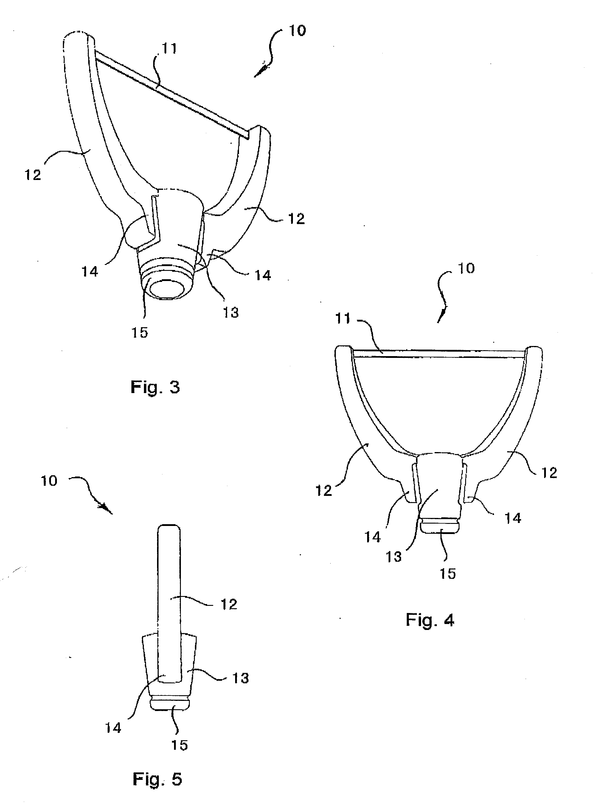
[0016]Firstly referring to FIGS. 1 and 2, the two figures show two views of a handle 2 of a flosser device 1 according to the present invention. The handle 2 comprises an upper portion used as a handgrip 3 for gripping, and a lower portion, i.e., a flosser element connecting mechanism 5 at the top of the handgrip for fixing a flosser element 10 (as shown in FIG. 3). The central portion of the handgrip 3 is indented to form a finger press location 4, which is provided with projecting net-like textures for facilitating a user tightly holding the handle 2 and controlling the flosser device 1. In addition, the flosser element connecting mechanism 5 is provided with flosser element connecting slots 6 at the tip of the handle 2. The flosser element connecting slots 6 are divided into a flosser element longitudinal connecting slot 7 and a flosser element transverse connecting slot 8 to assist the flosser element 10 (as shown in FIG. 3) in being longitudinally or transversely mounted into t...


PUM


Abstract

The present invention relates to a dental cleaning device, particularly to a flosser device for cleaning teeth gaps. The flosser device according to the present invention removes food particles from different tooth gaps by mounting the flosser element to the flosser element longitudinal connecting slot and the flosser element transverse connecting slot to adjust the position of the flosser. The flosser element base is disposed in the gradually narrowing flosser element connecting slots, so that the flosser element arms diverse outwardly to tension a length of flosser between the flosser element arms. Besides, the center of the flosser element connecting slot is hollow to form a base receiving hole so that the base press-release point projects through the base receiving hole out of the handle after the flosser element base is mounted on the flosser element connecting mechanism, and a user can draw out the flosser element by pressing the base press-release point for replacement.

Description

TECHNICAL FIELD[0001]The present invention relates to a dental cleaning device, particularly to a flosser device for cleaning teeth gaps.BACKGROUND[0002]Currently, there are many methods of cleaning tooth gaps that range from toothpick to flossers which can all substantially realize the cleaning purpose. A toothpick is an elongated device with a pointed end, whereby the waste and food particles are removed by moving the pointed end through the tooth gaps. A flosser is a linear object, whereby waste and food particles in the tooth gaps are removed by putting the flosser through the tooth gaps when tightly griping two ends of the flosser. Yet, the above methods are difficult to implement so that inconvenience is caused to a user.[0003]There are a lot of known technologies in the market targeted at the above problems. One is the US 2003 / 0098037 entitled (“Dental Floss Device” published on May 29, 2003, wherein a user can tightly grip the handle of the floss device in cooperation with t...

Claims


Application Information

Patent Timeline
Patent Type & Authority Applications(United States)
IPC IPC(8): A61C15/04
CPCA61C15/048A61C15/046
Inventor YIM, WINGCHUN
Owner CONXEPT
Why Eureka
Try Eureka