
Method of dividing coverage area for robot and device thereof

a technology of robot and coverage area, applied in the direction of instrumentation, electrical programme control, program control, etc., can solve the problems of difficult to determine the exact location of the robot, the outline of obstacles or walls may not be smooth and considerably uneven, and the inability to effectively perform specific tasks for the whole area, etc., to achieve the effect of effective work

Active Publication Date: 2008-02-21
SAMSUNG ELECTRONICS CO LTD
View PDF6 Cites 48 Cited by
  • Summary
  • Abstract
  • Description
  • Claims
  • Application Information

AI Technical Summary

Benefits of technology

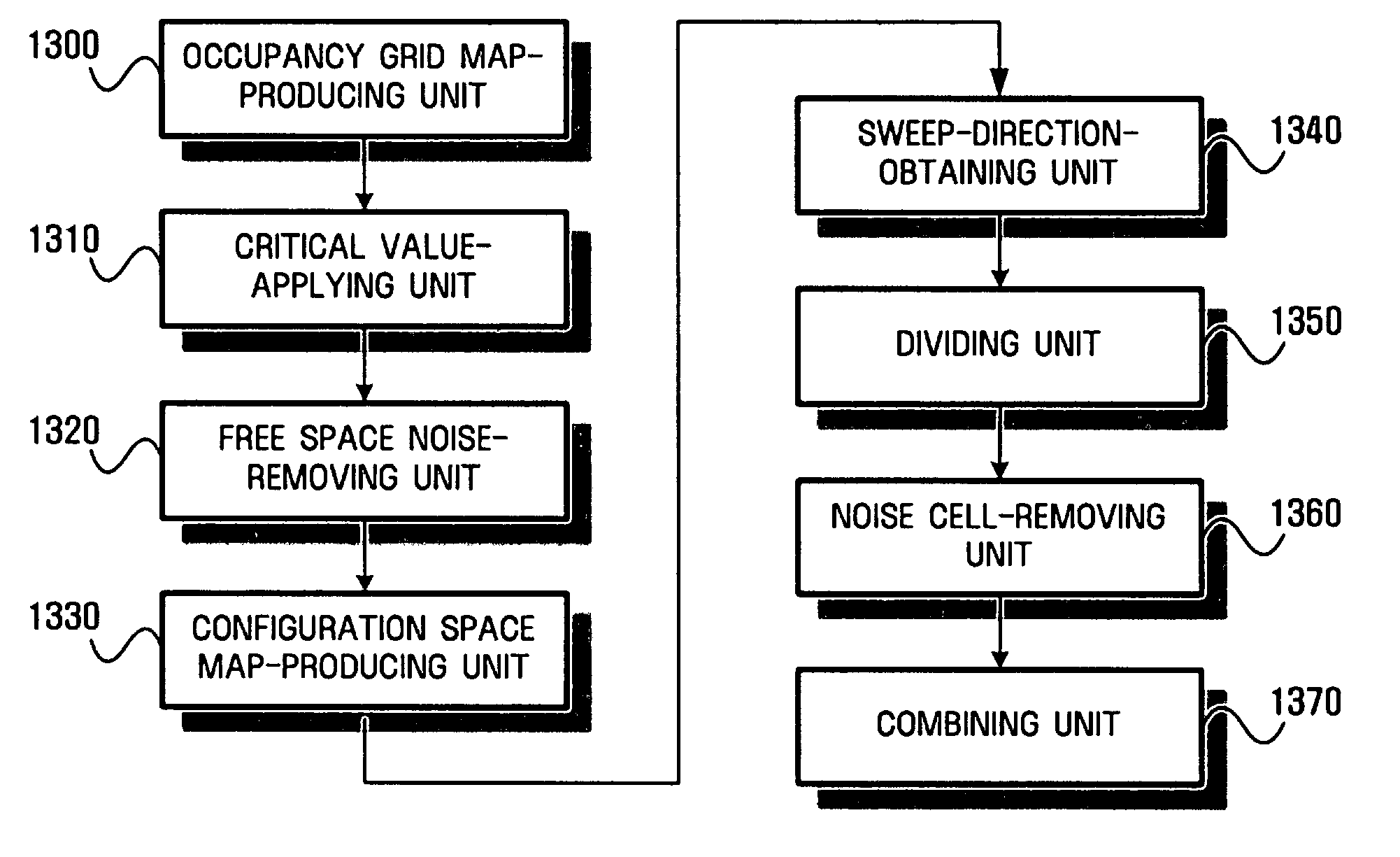
[0014]It is another aspect of the present invention to provide an area where a robot can effectively work by removing noise cells and combining unnecessarily divided segments.
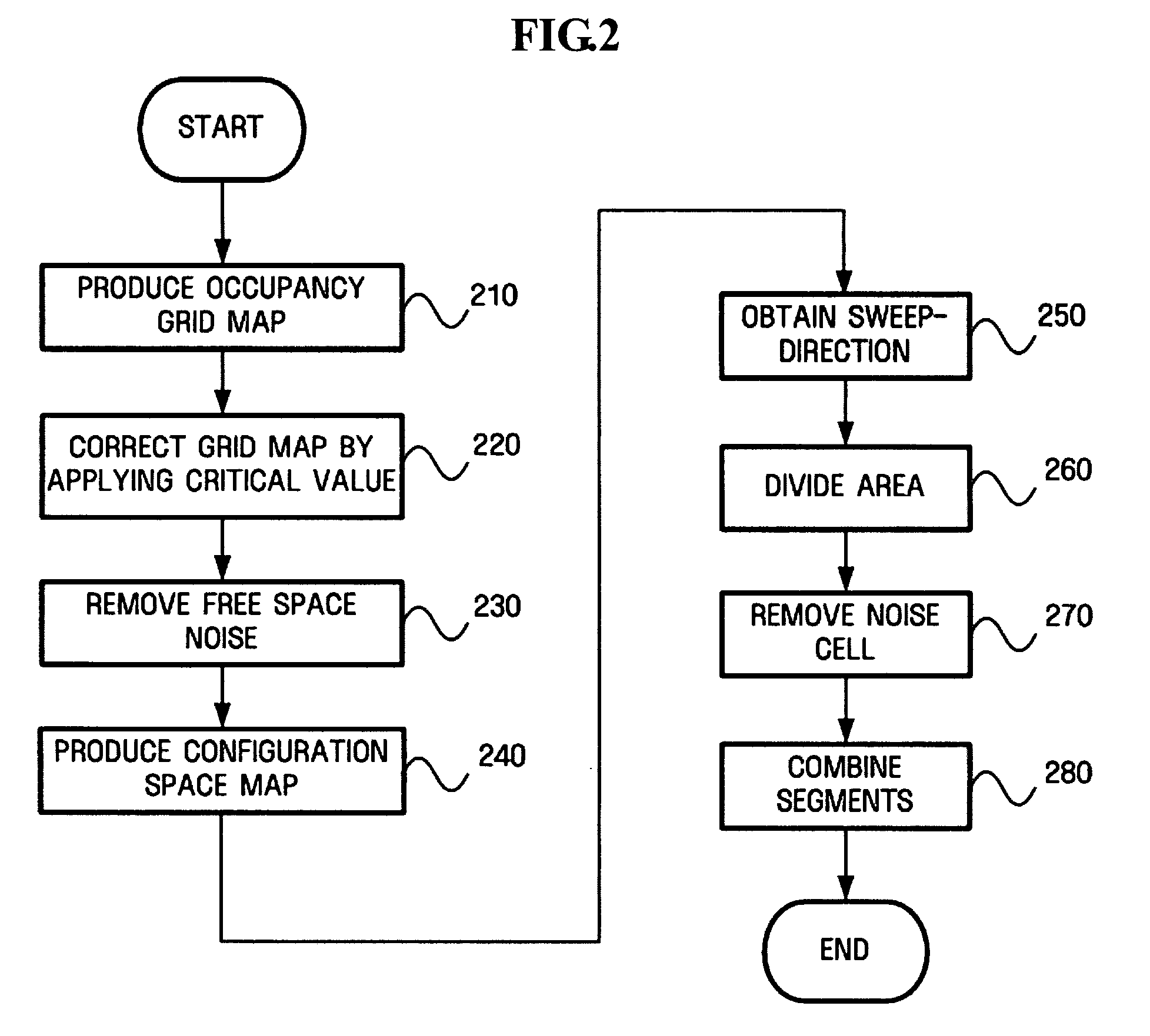
[0016]These and / or other aspects of the present invention are achieved by providing a method of dividing a coverage area for robot, the method including producing an occupancy grid map including grid points which are probabilistically distributed by sensing a distance from an obstacle, producing a configuration space map by increasing the thickness of an obstacle and a wall in the occupancy grid map based on a radius and a size of the robot, and dividing an area by sweeping the area with a band-typed slice in the configuration space map.

Problems solved by technology

However, when an intended region is large, if the robots randomly travel or work at random place in the area, they cannot effectively perform specific jobs for the whole area.
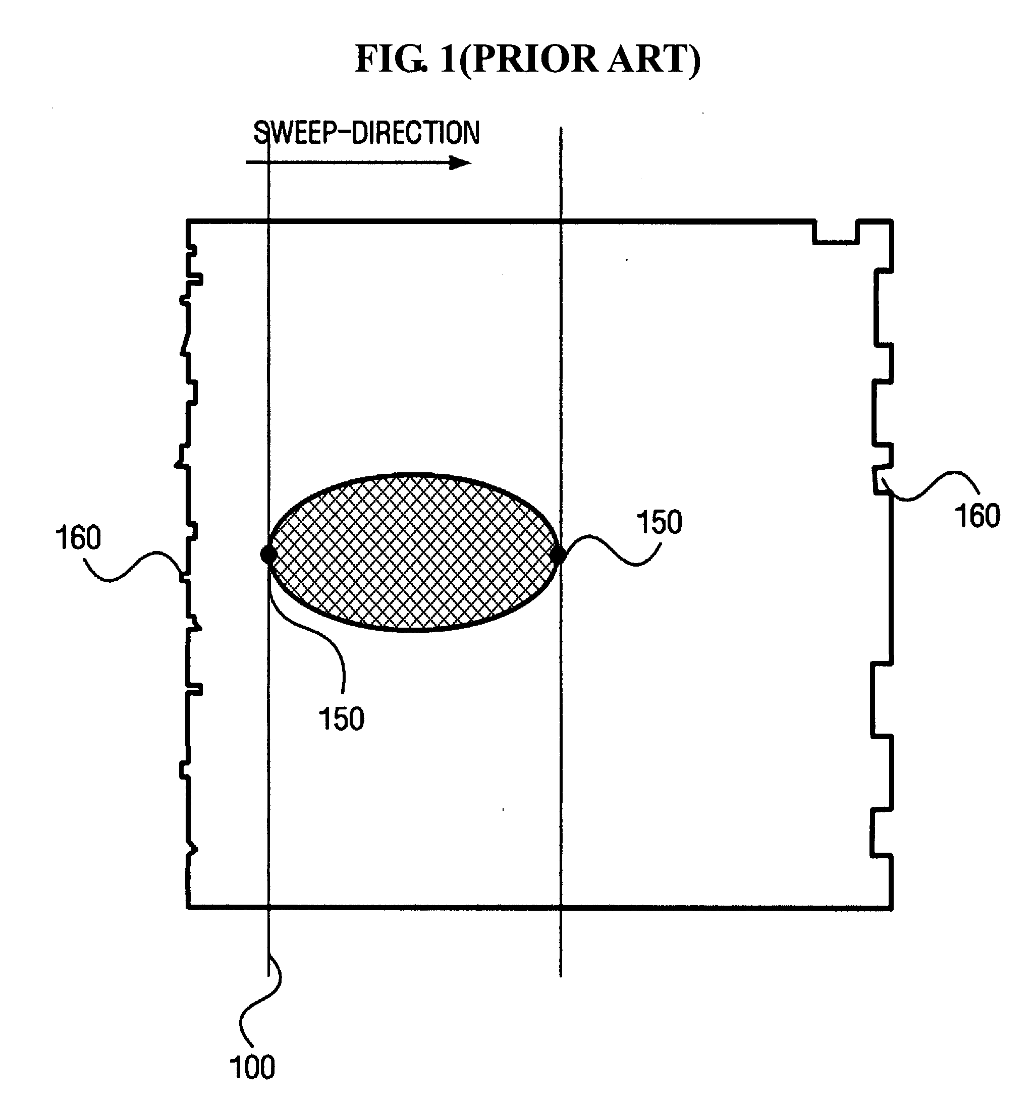
However, as for a grid map that is recognized by a robot with a distance measuring sensor, the outlines of obstacles or walls may not be smooth and considerably uneven.
Therefore, because the robot may always variably travel within tolerances for the sensor and it is difficult to determine the exact location of the robot and errors in relative distances from walls and obstacles may be created accordingly.

Method used


Image

  • Method of dividing coverage area for robot and device thereof
  • Method of dividing coverage area for robot and device thereof
  • Method of dividing coverage area for robot and device thereof

Examples


Embodiment Construction

[0036]Reference will now be made in detail to the embodiments of the present invention, examples of which are illustrated in the accompanying drawings, wherein like reference numerals refer to the like elements throughout. The embodiments are described below to explain the present invention by referring to the figures.

[0037]Reference will now be made in detail to the embodiments of the present invention, examples of which are illustrated in the accompanying drawings, wherein like reference numerals refer to like elements throughout. The embodiments are described below to explain the present invention by referring to the figures. The present invention may, however, be embodied in many different forms and should not be construed as being limited to the embodiments set forth herein. Rather, these embodiments are provided so that this disclosure will be thorough and complete and will fully convey the concept of the invention to those skilled in the art.

[0038]FIG. 2 is a flowchart illust...


PUM


Abstract

A method of dividing a coverage area of a robot and a device for the same. That is, a method of producing a space map for a robot to work and dividing the space map into at least one segment and a device for the same. The method includes producing an occupancy grid map composed of grid points that are probabilistically distributed by sensing a distance from an obstacle, producing a configuration space map by increasing the thickness of an obstacle and a wall in the occupancy grid map on the basis of the radius and size of the robot, and dividing an area by sweeping the area with a band-typed slice in the configuration space map.

Description

CROSS-REFERENCE TO RELATED APPLICATIONS[0001]This application claims priority from Korean Patent Application No. 10-2006-0078398 filed on Aug. 18, 2006 in the Korean Intellectual Property Office, the disclosure of which is incorporated herein by reference in its entirety.BACKGROUND OF THE INVENTION[0002]1. Field of the Invention[0003]The present invention relates to a method of dividing a coverage area for a robot and a device of the same. More particularly, to a method of producing a space map for a robot to work and dividing the space map into at least one segment and a device of the same.[0004]2. Description of the Related Art[0005]Conventional robots have been designed for automatic processes in factories or industries. As an automatic control technology and remote control technology have been developed, robots have been used for simple work or work under extreme environments, such as high or low temperature, or in dangerous environments such as the outer space or the sea floor....

Claims


Application Information

Patent Timeline
IPC IPC(8): G05B19/04
CPCG05D1/0219G05D1/0274G05D2201/0203B25J9/00B25J19/00
Inventor MYEONG, HYEONBANG, SEOK-WONKANG, JUNG-WONKIM, SI-JONGCHUNG, MYUNG-JINLEE, SU-JINN
Owner SAMSUNG ELECTRONICS CO LTD
Learn More