
Multiple View Display

a multi-view display and display technology, applied in the field of multi-view display, can solve the problems of poor image quality of lenticular screens, poor anti-reflection performance, and scattering of practicable lenses, and achieve the effects of reducing manufacturing problems, facilitating display, and increasing thickness

Active Publication Date: 2008-02-21
SHARP KK
View PDF11 Cites 50 Cited by
  • Summary
  • Abstract
  • Description
  • Claims
  • Application Information

AI Technical Summary

Benefits of technology

[0059] It is thus possible to provide an improved multiple view display. Embodiments and examples of such a display may achieve combinations of one or more of the following advantages:
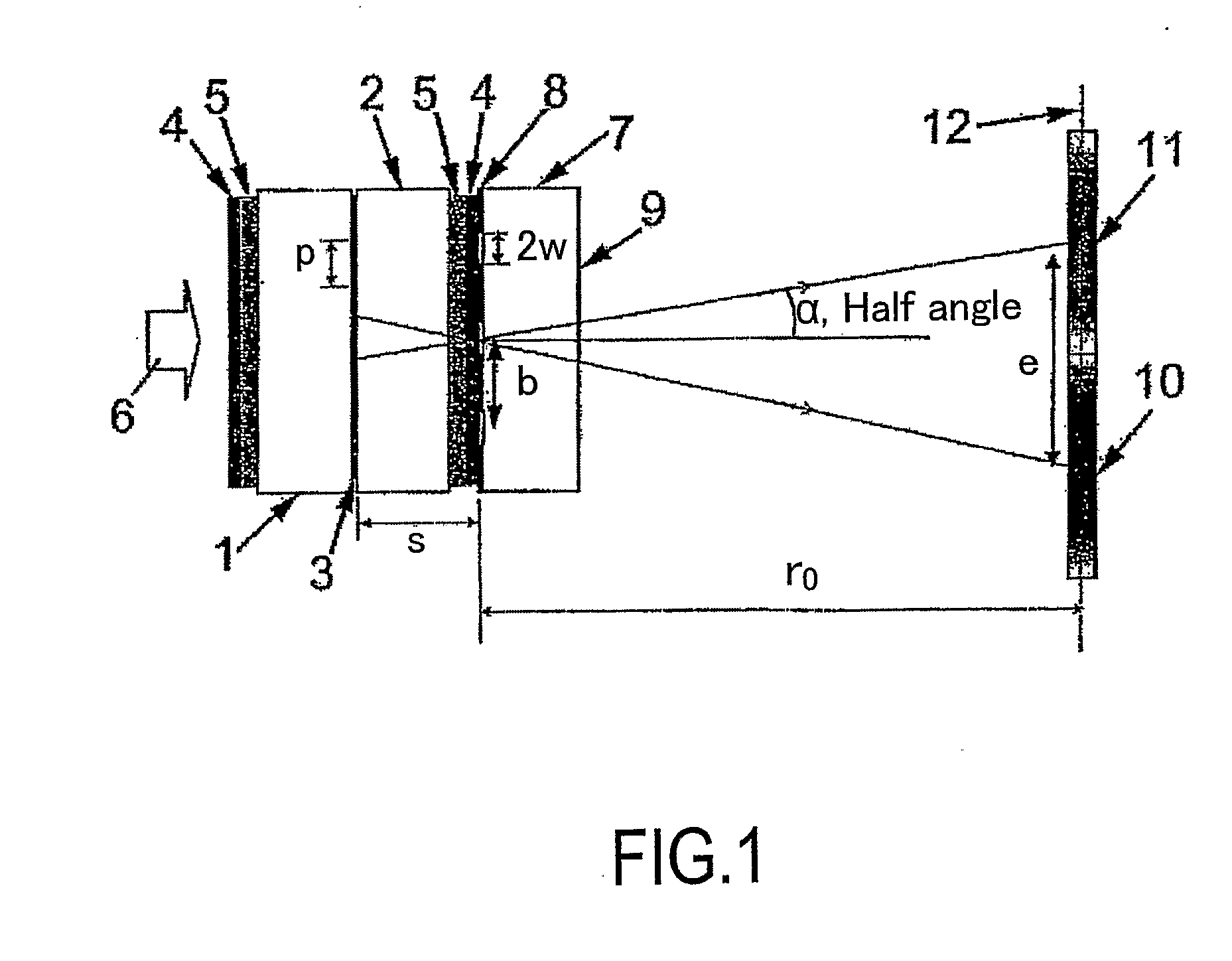
[0064] Pn displays where n is greater than one provide an advantage in that the space in between a pixel plane of the spatial light modulator and a plane containing the parallax elements may be made greater than for P1 displays. Thus, any substrate between the planes can be of larger thickness and this reduces manufacturing problems, for example in handling relatively thin glass. In addition, it makes it possible or easier for the parallax optic, such as a parallax barrier, to be of an active type without requiring the use of thin substrates such as thin glass. It is therefore easier to provide a display which is switchable between multiple view and single view modes. For example, a parallax barrier can be embodied by a liquid crystal device which can be switched to a substantially uniform transmissive mode so as effectively to disable the parallax barrier and permit normal viewing of a single image or view throughout a wide viewing region.

Problems solved by technology

Practical lenses tend to suffer from scatter and poor anti-reflection performance so that the surface is very visible in both ambient and backlit environments.
Therefore, the image quality of lenticular screens can be poor and the system suffers from similar problems as parallax barriers such as the need for close proximity to the image pixels.
Holographic methods of image splitting also exist but they suffer from viewing angle problems, pseudoscopic zones and a lack of easy control of the images.
However, such displays have disadvantages in that the barrier structure may be more visible to the viewer and colour defects as described hereinafter may be produced.
The effect of this is that each red column of pixels of the left eye view becomes increasingly obscured.

Method used


Image

  • Multiple View Display
  • Multiple View Display
  • Multiple View Display

Examples


Embodiment Construction

[0084] Like reference numerals refer to like parts throughout the drawings.

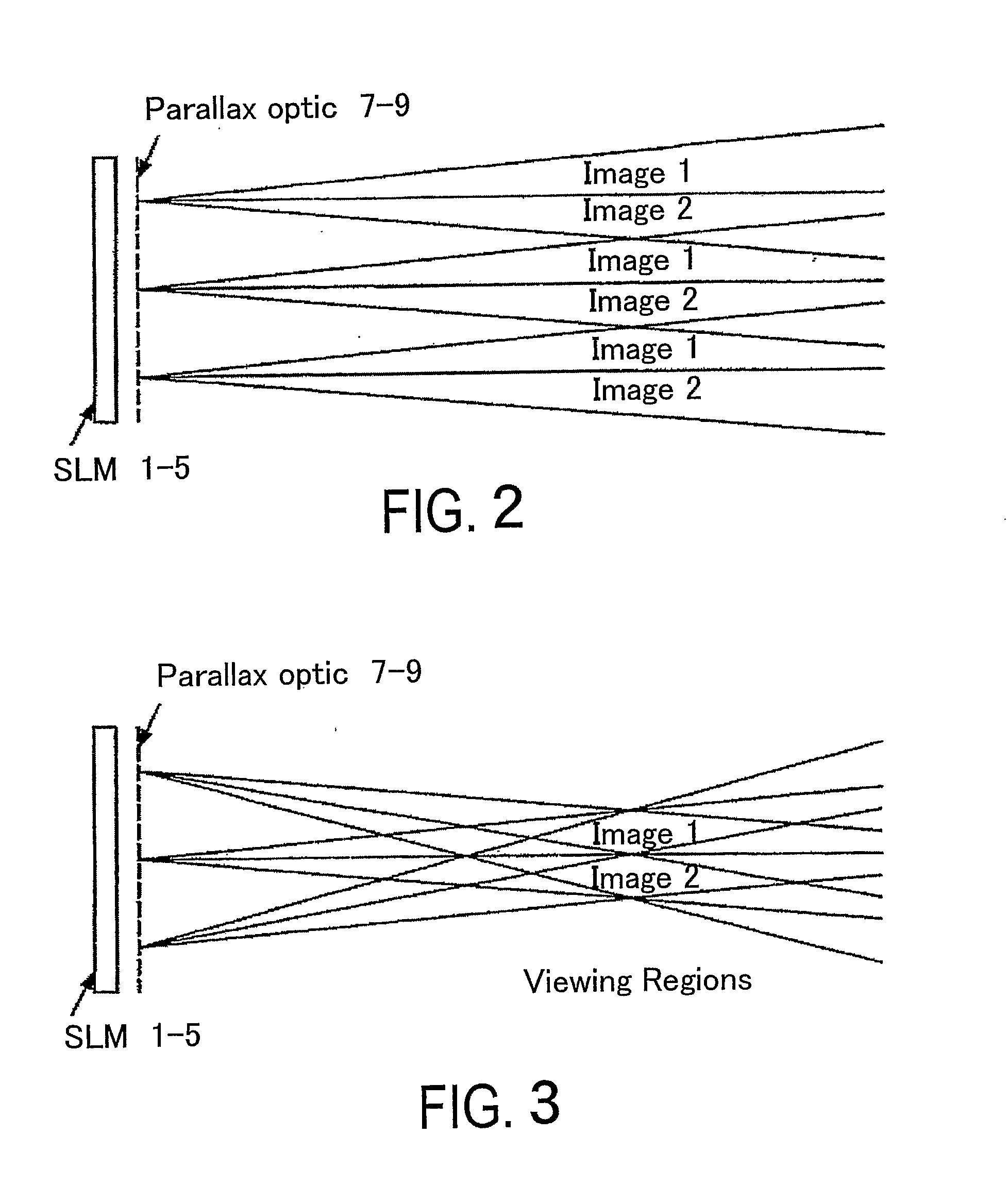
[0085] The multiple view displays described hereinafter are all of the two or dual view type but displays providing more than two views may also be provided. The displays may be used for any suitable application such as autostereoscopic 3D image display and display to more than one viewer of images which may be independent and unrelated to each other. All of the displays are colour displays made up of red, green and blue pixels with triplets of RGB pixels forming a composite colour or “white” group. However, other arrangements are possible, such as composite groups comprising RGGB pixels or RGYB pixels, where Y pixels are white. The displays comprise flat panel liquid crystal devices as the spatial light modulators and parallax barriers as the parallax optics. However, other types of spatial light modulators (including light-emitting types) and other types of parallax optics may be used.

[0086] The P2 displa...


PUM


Abstract

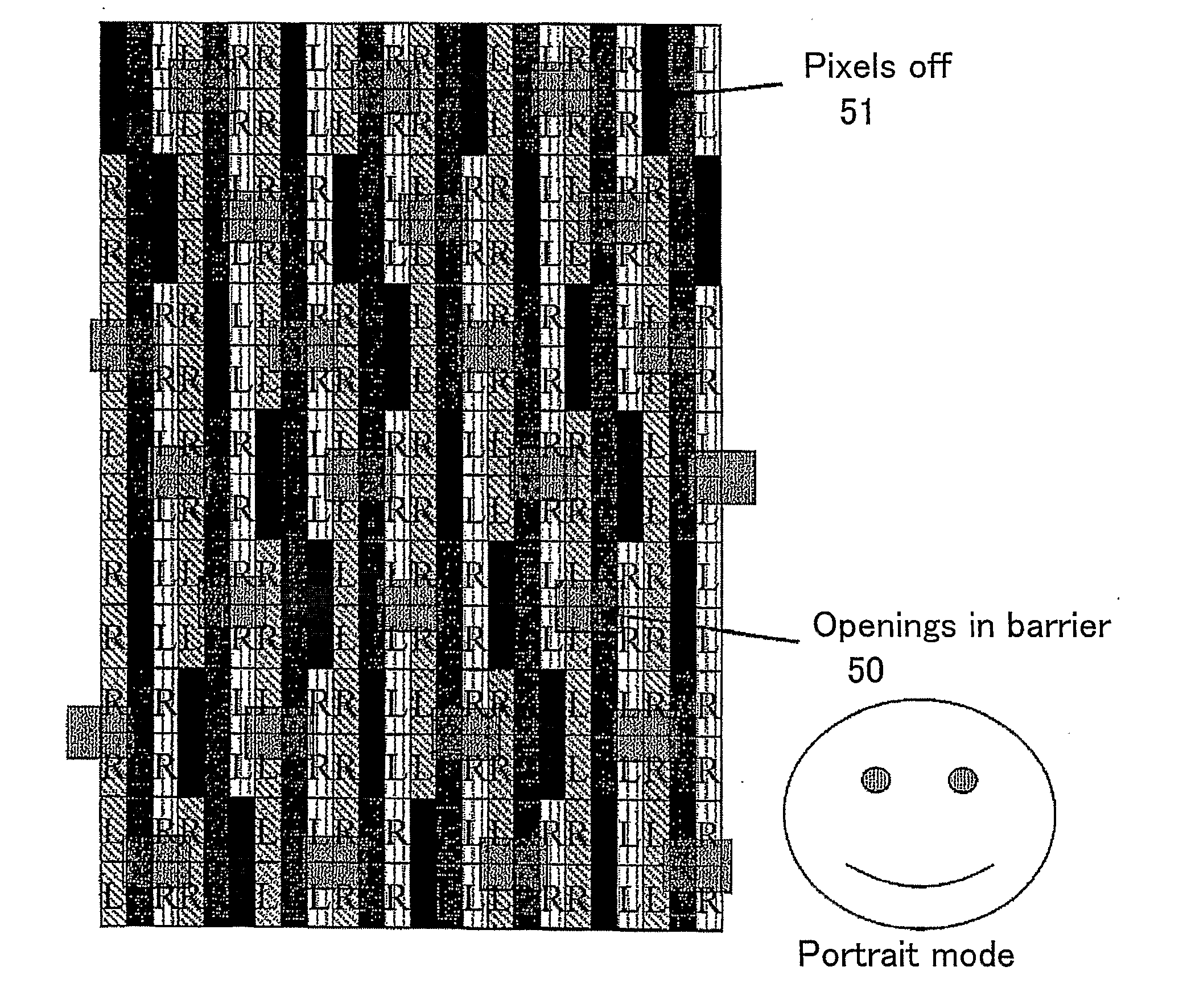
A multiple view display comprises a parallax optic such as a parallax barrier (25) and a spatial light modulator (20) having a plurality of pixels arranged as rows and columns. The parallax optic (25) cooperates with the pixel structure to create a plurality of primary viewpoint-corrected viewing windows. The rows are arranged as groups and the parallax elements are arranged as rows. Each parallax element is aligned with a respective group of rows of the pixels. The pixels comprise sets of pixels of different colours arranged so that the sequence of visible colours viewable in each viewing window through each parallax element of each row of parallax elements is different from the sequence of pixel colours visible through the or each nearest parallax element in the or each adjacent row of parallax elements.

Description

TECHNICAL FIELD [0001] The present invention relates to a multiple view display. [0002] Such displays may be used, for example, when two or more different people need to see two or more different images on the same display screen. The viewing angle difference is preferably quite large (around 60 degrees) between viewers. [0003] Such displays may also be used as three-dimensional (3D) displays, especially autostereoscopic displays. Such displays may be used in 3D mobile handsets, 3D games, 3D computer monitors, 3D laptop displays, 3D workstations and 3D professional imaging (e.g. for medical, design or architectural usage). In some 3D displays, it is necessary to increase the eye separation distance for a particular viewing distance or decrease the viewing distance for a particular eye separation. Both of these cases require a wider separation angle. BACKGROUND ART [0004] In normal vision, the two human eyes perceive views of the world from different perspectives due to their separat...

Claims


Application Information

Patent Timeline
IPC IPC(8): H04N7/00G02B30/31G09F19/12G09F19/14H04N13/00
CPCG02B27/2214G09F19/12G09F19/14H04N13/0452H04N13/0415H04N13/0422H04N13/0447H04N13/0413H04N13/324H04N13/356H04N13/315H04N13/317H04N13/351G02B30/31G02B30/24G02B30/27G09F19/125
Inventor EVANS, ALLANMATHER, JONATHANJONES, GRAHAM
Owner SHARP KK
Learn More