
Carriage wheel ocean turbine

a technology of ocean turbines and rolling carriages, which is applied in the direction of electric generator control, machines/engines, mechanical equipment, etc., can solve the problems of limited size, limited blade or vane angle control, and inability to control the structural control of blades or vanes upon rolling carriages

Inactive Publication Date: 2008-02-21
JOHNSON TIMOTHY RONALD
View PDF10 Cites 10 Cited by
  • Summary
  • Abstract
  • Description
  • Claims
  • Application Information

AI Technical Summary

Problems solved by technology

While these designs function well, they limit the size and therefore the power of the dynamo to be turned.
While elegant and efficient, perhaps, in its intended size range, it is limited in size, and therefore power by the solid shroud ring.
Thus the structural control of blade or vane angle upon the rolling carriage is unavailable.
This is unnecessary in his “Peripheral Turbine Support System” because he is depicting only rigid vane structures. Mr. Lusk's system also does not anticipate higher tensile loading of the vane ends than is required for stability of the rigid system.

Method used


Image

  • Carriage wheel ocean turbine
  • Carriage wheel ocean turbine
  • Carriage wheel ocean turbine

Examples


embodiment

Initial Embodiment

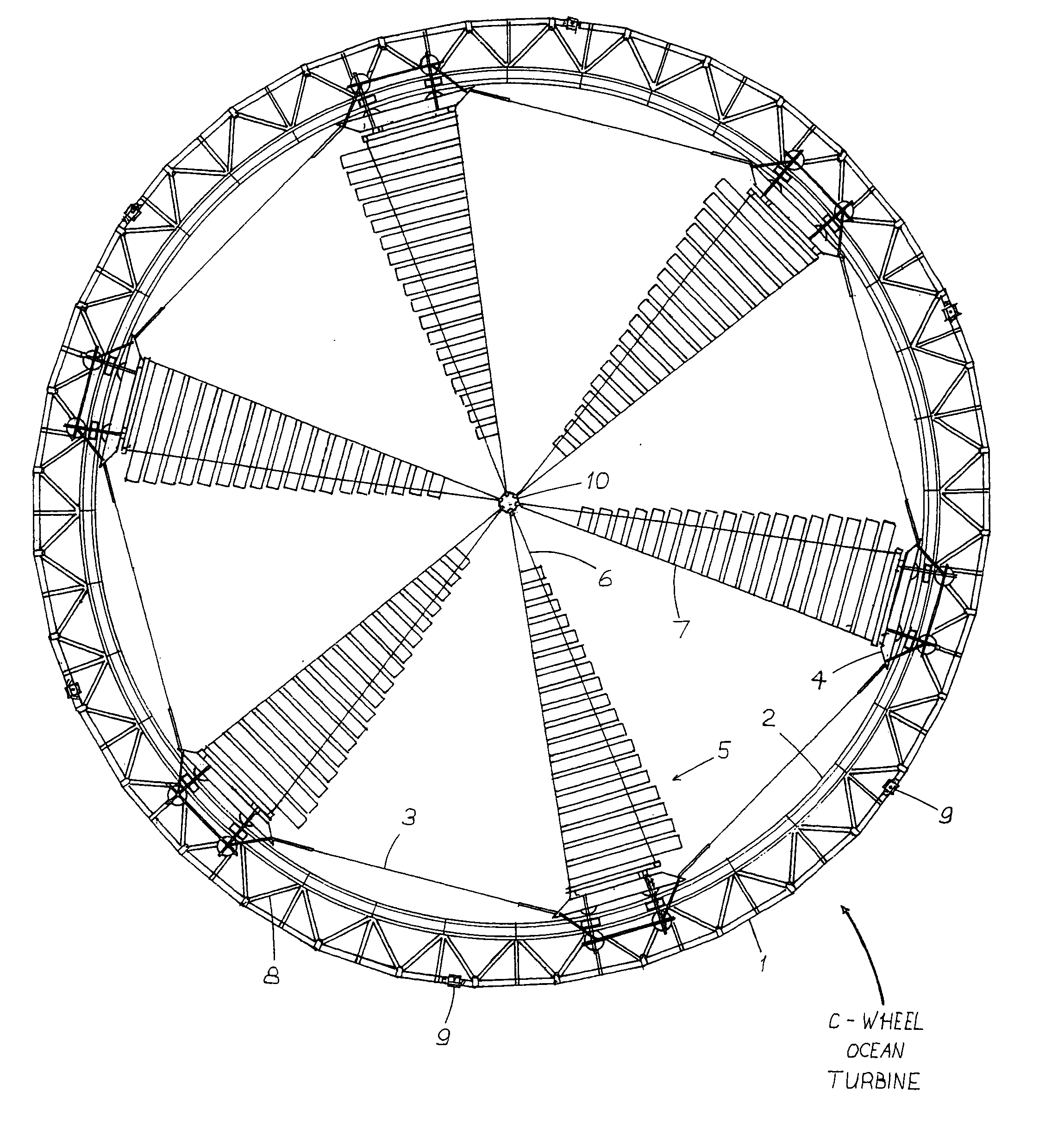
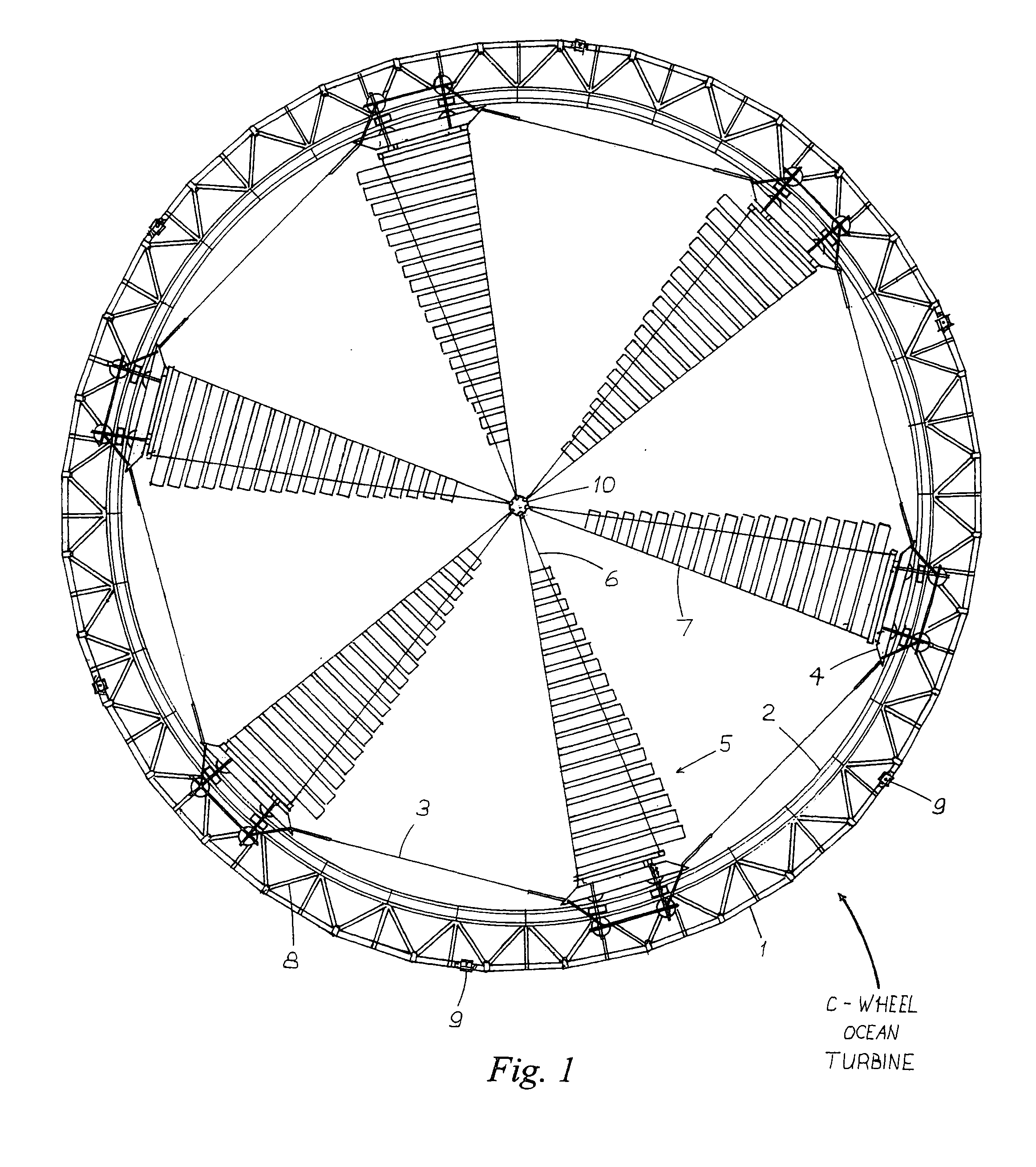
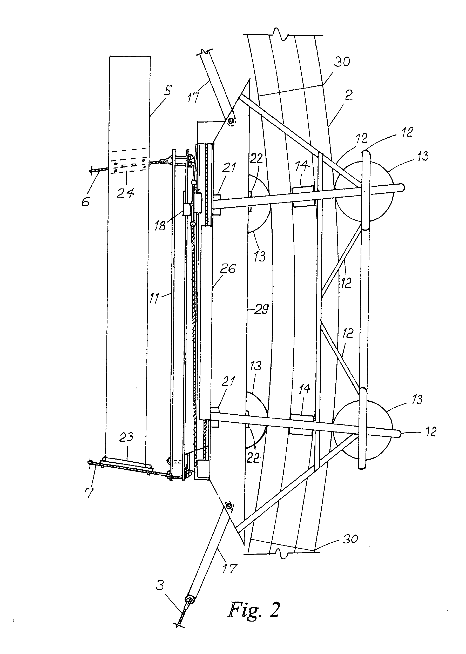
Tracks—FIGS. 1,2,3,4,5

[0020] The two tracks are circular, as shown in FIG. 1, and are connected by struts to each other to form a parallel arrangement, as shown in FIG. 2. The twin tracks are both connected to a third ring as shown in FIGS. 1 and 3. They are of octagonal outer sectional contour, with a concentric round space for air or water inside. The tracks will be required to withstand large forces resulting in compression, tension, and shear, but must also provide “roadways” for the wheels and contribute to buoyancy compensation. Reinforced concrete is one material which can meet these requirements.

[0021] Each of the two tracks is made up of a chosen number of identical pieces. In the example shown, the arc each segment describes comprises a 10 degree sweep from the center of the finished circle, so 36 are required to form each track. The material in the original design is reinforced concrete, using stainless steel throughout the precision-built reinforcemen...


PUM


Abstract

A turbine wheel on a horizontal axis is constructed on a network of cables radially and circumferentially connected and supported centrifugally by a ring with a friction-reduction method to permit turning within said ring. The ring structure is composed of buoyancy-controlled modules to allow construction of extremely large systems deployable in ocean depths. Electrical equipment can be variously attached for generation of power.

Description

CROSS-REFERENCE TO RELATED APPLICATIONS [0001] This application claims the benefit of PPA Ser. No. 60 / 818,618, filed 2006 Jul. 5 by the present inventor, which is incorporated by reference.BACKGROUND [0002] 1. Field of Invention [0003] This invention relates to fluid current motors deployable in ocean currents for power generation. There is a vast untapped supply of useful energy in the regular movement of the Earth's oceans. We have yet to develop any significant portion of it. This is due to the hostility of the ocean depths to us and our machinery generally. Conquest of this realm and the harvest of its ever-renewing energies is an ancient dream. Recent developments in technology have impelled us to think it is possible. The driving needs of our civilization and the threat posed to it by the increasingly difficult task of meeting those needs with the non-renewable sources on which we now rely have set the stage for a major effort. The moon did not refuse man's footsteps, nor will...

Claims


Application Information

Patent Timeline
IPC IPC(8): F03B13/10
CPCF03B13/262Y02E10/28F05B2240/97F03B17/061Y02E10/30Y02E10/20
Inventor JOHNSON, TIMOTHY RONALD
Owner JOHNSON TIMOTHY RONALD
Learn More