Chip package structure and circuit board thereof

a technology of chip package and circuit board, which is applied in the direction of printed circuit manufacturing, printed circuit stress/warp reduction, printed circuit aspects, etc., can solve the problems of reducing the area available for disposing circuit layers, reducing yield, and poor product reliability, so as to reduce the probability of trace pulling apart

Active Publication Date: 2008-02-21
ADVANCED SEMICON ENG INC
View PDF7 Cites 11 Cited by
  • Summary
  • Abstract
  • Description
  • Claims
  • Application Information

AI Technical Summary

Benefits of technology

[0009]The present invention is directed to providing a chip package structure and a circuit board thereof, so as to reduce the probability of the trace being pulled apart by the stress generated when removing redundant encapsulant.
[0024]In the chip package structure and circuit board thereof according to the present invention, because a dummy trace or an enlarged section of the trace is used, it can help the trace to resist the stress generated when removing the redundant encapsulant after forming the encapsulant, and reduce the probability of the trace being pulled apart by the stress. Moreover, in the chip package structure according to the present invention, the corner of the area covered by the encapsulant can still be used to dispose the traces. Therefore, compared with the other conventional art, the present invention has a large trace layout space.

Problems solved by technology

The trace 122 at the corner of the encapsulant disposing area 132 is located at a position where the stress is concentrated, and thus is easily to be pulled apart by the stress, which causes a decreased yield and poorer product reliability.
However, such a method reduces the area on the substrate available for disposing the circuit layer, so that the layout of the trace is more difficult to design.

Method used


Image

  • Chip package structure and circuit board thereof
  • Chip package structure and circuit board thereof
  • Chip package structure and circuit board thereof

Examples


first embodiment

The First Embodiment

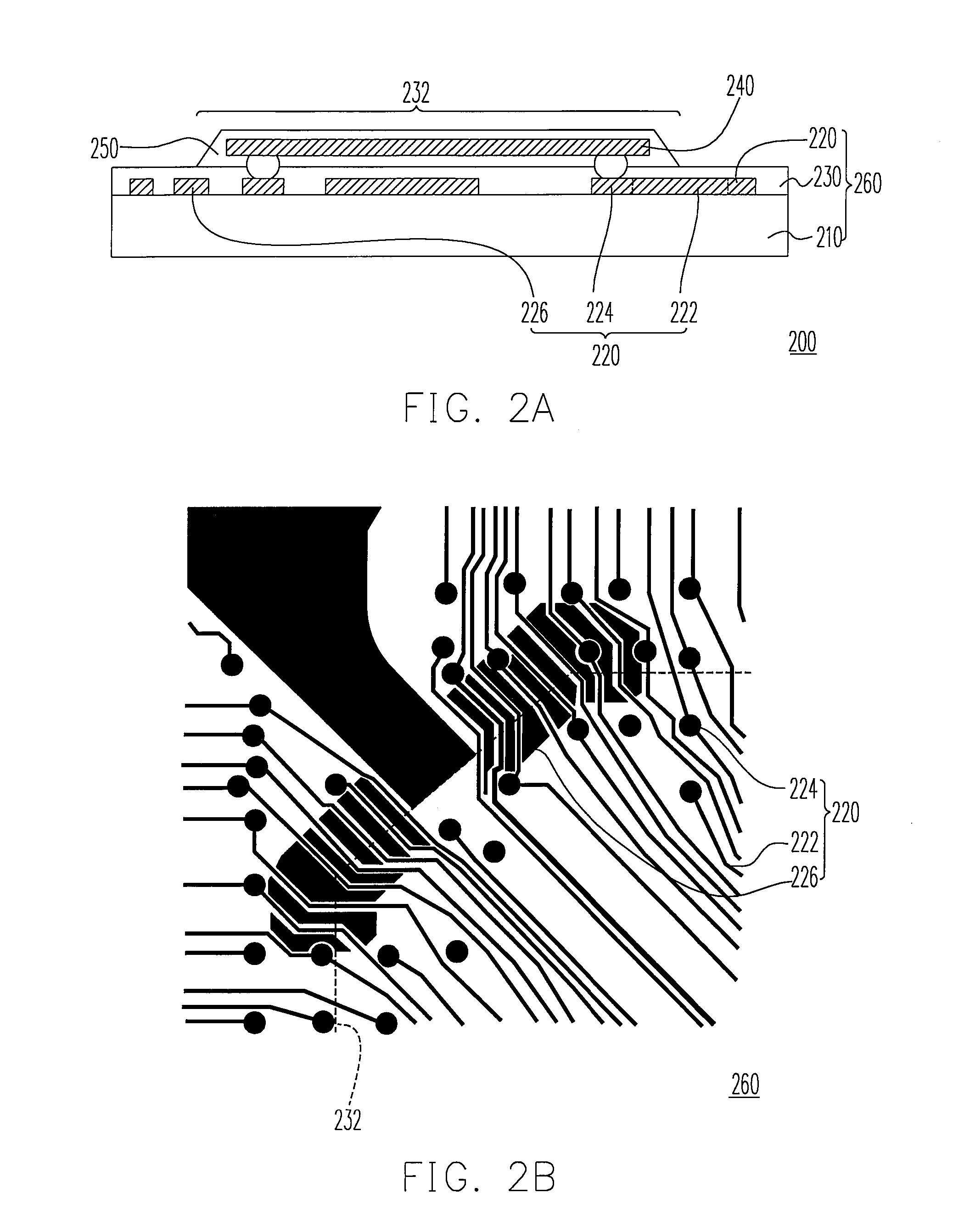
[0037]FIG. 2A is a schematic sectional view of a chip package structure having a circuit board according to a first embodiment of the present invention, and FIG. 2B is a schematic top view of a corner of the circuit board according to the first embodiment of the present invention. Referring to FIGS. 2A and 2B, the chip package structure 200 includes a circuit board 260, a chip 240, and an encapsulant 250. The circuit board 260 includes a substrate 210, a circuit layer 220, and a solder mask 230. The circuit layer 220 is disposed on the substrate 210 and includes a plurality of traces 222, a plurality of via holes 224, and a dummy trace 226. The dummy trace 226 is located between two adjacent traces 222, and the dummy trace 226 is electrically isolated from the traces 222 and the via holes 224. Moreover, the materials of the dummy trace 226, the traces 222, and the via holes 224 are, for example, the same conductive material, so as to form the traces 222, the via ...

second embodiment

The Second Embodiment

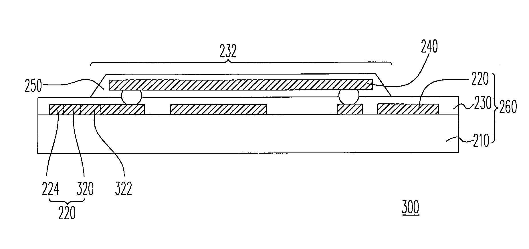
[0040]FIG. 4A is a schematic sectional view of a chip package structure having a circuit board according to a second embodiment of the present invention, and FIG. 4B is a schematic top view of a corner of the circuit board according to the second embodiment of the present invention. Referring to FIGS. 4A and 4B, a chip package structure 300 and a circuit board 310 thereof in the second embodiment are substantially the same as the chip package structure 200 and the circuit board 260 thereof in the first embodiment respectively, except that the chip package structure 300 and the circuit board 310 thereof do not have the dummy trace 226, but one trace 320 has an enlarged section 322 instead. A line width A of the enlarged section 322 of the trace 320 is larger than a line width B of the other portion of the trace 320.

[0041]Since the enlarged section 322 increases the contact area of the circuit layer 220 and the substrate 210, in which the circuit layer 220 is disp...


PUM


Abstract

A chip package structure including a substrate, a circuit layer, a solder mask, a chip, and an encapsulant is provided. The circuit layer is disposed on the substrate and includes two traces and a dummy trace. The dummy trace is disposed between the traces. The solder mask covers the circuit layer and the substrate. The chip is disposed on the solder mask and electrically connected to the traces. The encapsulant covers the solder mask and wraps the chip. The traces and the dummy trace extend from the inside of the area covered by the encapsulant to the outside of the area covered by the encapsulant. Because the dummy trace is used in the chip package structure, it can be avoided that the traces is pulled apart when the redundant encapsulant is removed after the encapsulant is formed.

Description

CROSS-REFERENCE TO RELATED APPLICATION[0001]This application claims the priority benefit of Taiwan application serial no. 95129848, filed on Aug. 15, 2006. All disclosure of the Taiwan application is incorporated herein by reference.BACKGROUND OF THE INVENTION[0002]1. Field of the Invention[0003]The present invention relates to a chip package structure and a circuit board thereof, and more particularly to a chip package structure and a circuit board thereof capable of resisting stress generated when removing a redundant encapsulant.[0004]2. Description of Related Art[0005]In modern life with progressing science and technology, 3C electronic products are widely used in people's life. The electronic products are developed towards the trend of being light, thin, short and small along with the increasing progress of the trend. When the demand of people for electronic products increases, diverse peripheral components of the electronic products are emerged, in which circuit board is one o...

Claims


Application Information

Patent Timeline
Patent Type & Authority Applications(United States)
IPC IPC(8): H01L23/04
CPCH01L23/49838H01L2224/16H05K1/0271H05K2201/10674H05K3/3452H05K2201/09781H05K3/284H01L2924/00014H01L2924/00011H01L2224/0401
Inventor HSIEH, CHING-CHUN
Owner ADVANCED SEMICON ENG INC
Why Eureka
Try Eureka