
Speech coding apparatus, speech decoding apparatus, speech coding method, speech decoding method, and computer readable recording medium

a speech decoding and speech signal technology, applied in the field of speech decoding apparatus, speech decoding apparatus speech decoding method, etc., can solve the problems of reducing the quality of the speech signal to be decoded by the speech decoding apparatus, and the quality of the reproduced speech becomes poorer, so as to improve the quality of the speech signal

Inactive Publication Date: 2008-02-14
CASIO COMPUTER CO LTD
View PDF9 Cites 11 Cited by
  • Summary
  • Abstract
  • Description
  • Claims
  • Application Information

AI Technical Summary

Benefits of technology

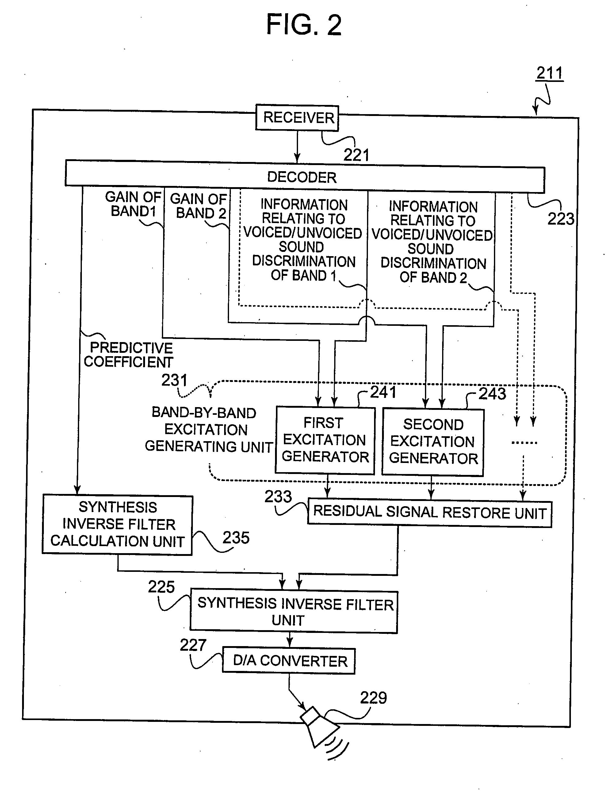
The present invention provides a speech coding and decoding apparatus that can improve the quality of a speech signal. This is achieved by performing a predictive analysis on a speech signal to acquire a predictive coefficient and a residual signal, and then coding the predictive coefficient and the band-by-band residual signal intensities for each band. The apparatus can also generate an excitation signal for each band, restore a residual signal from the excitation signals, and combine the predictive coefficient and the restored residual signal to restore a speech. The technical effect of this invention is to improve the quality of speech signals during coding and decoding.

Problems solved by technology

While the analysis-synthesis speech compression technique can make the bit rate lower than the waveform coding type speech compression technique, the quality of a reproduced speech becomes poorer.
However, the conventional band-by-band processing of a residual signal does not take the band dependency of the intensity of a residual signal into account.
Therefore, band-by-band processing of a residual signal considering no band dependency of the intensity of the residual signal can cause reduction in the quality of a speech signal to be decoded by the speech decoding apparatus.

Method used


Image

  • Speech coding apparatus, speech decoding apparatus, speech coding method, speech decoding method, and computer readable recording medium
  • Speech coding apparatus, speech decoding apparatus, speech coding method, speech decoding method, and computer readable recording medium
  • Speech coding apparatus, speech decoding apparatus, speech coding method, speech decoding method, and computer readable recording medium

Examples


Embodiment Construction

[0063] A speech coding apparatus and a speech decoding apparatus according-to a preferred embodiment of the present invention will be elaborated below with reference to the accompanying drawings.

[0064]FIG. 1 is a functional configuration diagram of a speech coding apparatus 111 according to the embodiment.

[0065] As shown in FIG. 1, the speech coding apparatus 111 includes a microphone 121, an A / D converter 123, a predictive analyzer 131, a band-pass filter unit 133, a gain calculation unit 135, a voiced / unvoiced discrimination and pitch extraction unit 137, a coder 125 and a transmitter 127.

[0066] The predictive analyzer 131 incorporates a predictive analysis inverse filter calculator 141.

[0067] The band-pass filter unit 133 has a first band-pass filter 151, a second band-pass filter 153, a third band-pass filter 155, and necessary band-pass filters (not shown) following the third band-pass filter 155.

[0068] The gain calculation unit 135 has a first gain calculator 161, a secon...


PUM


Abstract

In a speech coding apparatus, a band-pass filter unit separates a residual signal generated by a predictive analyzer into band by band components. Then, a gain calculation unit and a voiced / unvoiced discrimination and pitch extraction unit acquire information on an intensity characterizing each band, information on a result of discrimination as to whether each band-by-band component is a voiced sound or unvoiced sound, and information on a pitch frequency when it is a voiced sound. The acquired information is coded together with a predictive coefficient and is transmitted to a speech decoding apparatus. The speech decoding apparatus generates an excitation signal while reflecting the feature of each band of the original residual signal. This makes the excitation signal an efficient replica of the original residual signal.

Description

BACKGROUND OF THE INVENTION [0001] 1. Field of the Invention [0002] The present invention relates to a speech coding apparatus, speech decoding apparatus, speech coding method, speech decoding method, and computer readable recording medium which execute analysis-synthesis speech coding and speech decoding processes. [0003] 2. Description of the Related Art [0004] In a speech compression technique used in cellular phones or the like, technical developments are being made to fulfill the restrictions that, for example, the sampling frequency is 8 kHz and the transmission / reception speed is 4 kbps. The speech compression technique is classified in a low bit-rate speech compression technique in analysis-synthesis speech compression techniques. [0005] A typical analysis-synthesis low bit-rate speech compression technique is, for example, an 8-kbps speech coding method specified in the ITU Recommendation G. 729. In this speech coding method, a speech coding apparatus mainly performs a line...

Claims


Application Information

Patent Timeline
Patent Type & Authority Applications(United States)
IPC IPC(8): G10L19/00G10L19/083G10L19/02G10L19/06G10L19/087G10L25/90G10L25/93
CPCG10L19/087
Inventor IDE, HIROYASU
Owner CASIO COMPUTER CO LTD
Learn More