
Power delivery system of hybrid vehicle

a technology of power delivery system and hybrid vehicle, which is applied in the direction of electric propulsion mounting, transportation and packaging, gearing, etc., can solve the problems of poor energy efficiency, rapid deterioration of system efficiency, and none of the problems have been completely satisfactory, so as to improve power delivery efficiency, prevent or reduce energy circulation, and high efficiency

Inactive Publication Date: 2008-02-14
HYUNDAI MOTOR CO LTD
View PDF2 Cites 15 Cited by
  • Summary
  • Abstract
  • Description
  • Claims
  • Application Information

AI Technical Summary

Benefits of technology

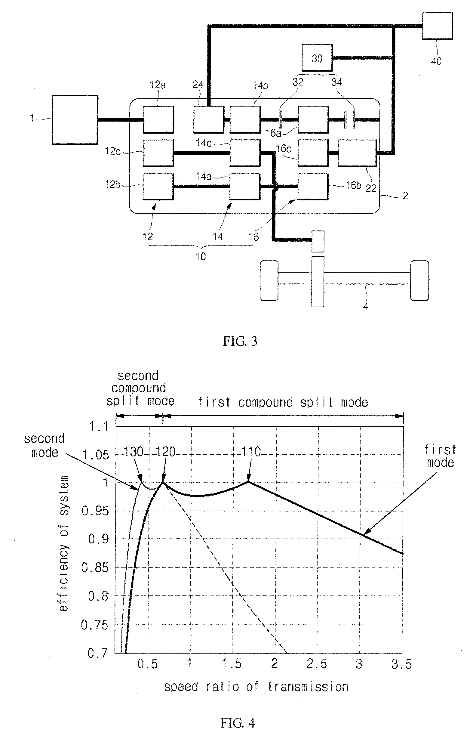
[0008]Embodiments of the present invention provide a power delivery system for hybrid vehicles having advantages of improving power delivery efficiency by changing the power delivery structure so as to prevent or reduce energy circulation and to allow the vehicle to drive at a high efficiency.
[0012]The clutch part may include: a first clutch connected to both the second planetary gear and the third planetary gear of the planetary gear part, and operating such that power generated by the engine and the first and second motor / generators can be delivered to a driving shaft; and a second clutch, one end of which is connected to the third planetary gear and the other end of which is connected to an inside of a transaxle housing, and operating to increase speed of the first motor / generator required for initial driving of the hybrid vehicle.

Problems solved by technology

However, in the series type, mechanical energy from an engine is stored in a battery and a vehicle is driven using a motor / generator, so there is a drawback of poor energy efficiency due to energy loss during energy conversions.
A problem of hybrid vehicles having either the series type or the parallel type is that energy circulation increases as a vehicle speed increases and thus an efficiency of a system is rapidly deteriorated.
Various power delivery types aimed at solving the problem of energy circulation have been investigated, but none have been completely satisfactory.

Method used


Image

  • Power delivery system of hybrid vehicle
  • Power delivery system of hybrid vehicle
  • Power delivery system of hybrid vehicle

Examples


Embodiment Construction

[0022]Reference will now be made in detail to various embodiments of the present inventions, examples of which are illustrated in the accompanying drawings and described below. While the inventions will be described in conjunction with exemplary embodiments, it will be understood that present description is not intended to limit the inventions to those exemplary embodiments. On the contrary, the inventions are intended to cover not only the exemplary embodiments, but also various alternatives, modifications, equivalents and other embodiments, which may be included within the spirit and scope of the invention as defined by the appended claims.

[0023]Referring to FIG. 1, a planetary gear part 10, which includes a first planetary gear 12, a second planetary gear 14 and a third planetary gear 16, is disposed within a transaxle housing 2. The first planetary gear 12 includes a first ring gear 12a, a first sun gear 12b and a first carrier 12c; the second planetary gear 14 includes a second...


PUM


Abstract

A power delivery system of a hybrid vehicle includes: a planetary gear part disposed including a first planetary gear, a second planetary gear, and a third planetary gear; a driving motor / generator part including a first motor / generator connected to the third planetary gear such that a power delivery can be performed therebetween, and a second motor / generator configured to deliver power to a driving shaft via the second planetary gear and supporting an engine in a starting state so as to operate the driving shaft; a clutch part connected to the planetary gear part such that the hybrid vehicle can drive by changing the operation mode at at least a critical mechanical point wherein the mechanical power of the driving motor / generator part is zero; and a controller controlling operations of the driving motor / generator part and the clutch part.

Description

CROSS-REFERENCE TO RELATED APPLICATION[0001]This application claims priority to and the benefit of Korean Patent Application No. 10-2006-0074774 filed in the Korean Intellectual Property Office on Aug. 8, 2006, the entire contents of which are incorporated herein by reference.BACKGROUND OF THE INVENTION[0002](a) Field of the Invention[0003]The present invention relates to a power delivery system of a hybrid vehicle and, more particularly to a system that can be driven by changing an operation mode of a transmission at at least a critical mechanical point.[0004](b) Description of the Related Art[0005]A hybrid vehicle is a vehicle that is driven by two power sources, for example, a gasoline engine and an electric motor / generator, a hydrogen engine and a fuel cell, a natural gas engine and a gasoline engine, a diesel engine and an electric motor / generator, of the like. Generally, a hybrid vehicle today uses a gasoline engine and an electric motor / generator as a power source.[0006]The p...

Claims


Application Information

Patent Timeline
Patent Type & Authority Applications(United States)
IPC IPC(8): F16H3/62
CPCB60K1/02B60K6/365B60K6/40B60K6/445B60K6/547B60W10/02Y02T10/6239B60W20/00F16H3/728F16H2037/102F16H2037/106F16H2200/201F16H2200/2035B60W10/08Y02T10/62B60K6/08B60W30/18127B60W20/40
Inventor CHO, SUNG TAELEE, JANG MOOKIM, NAM WOOK
Owner HYUNDAI MOTOR CO LTD
Learn More