
Energy converter

a technology of energy converter and energy storage, which is applied in the direction of engines without rotary main shafts, machines/engines, engine starters, etc., can solve the problems of reducing the efficiency of the system and the type of equipment, and achieve the effect of small energy storage, reduced cost and weight of energy converters, and very efficient operation

Inactive Publication Date: 2008-02-14
VOLVO CAR CORP +1
View PDF13 Cites 67 Cited by
  • Summary
  • Abstract
  • Description
  • Claims
  • Application Information

AI Technical Summary

Benefits of technology

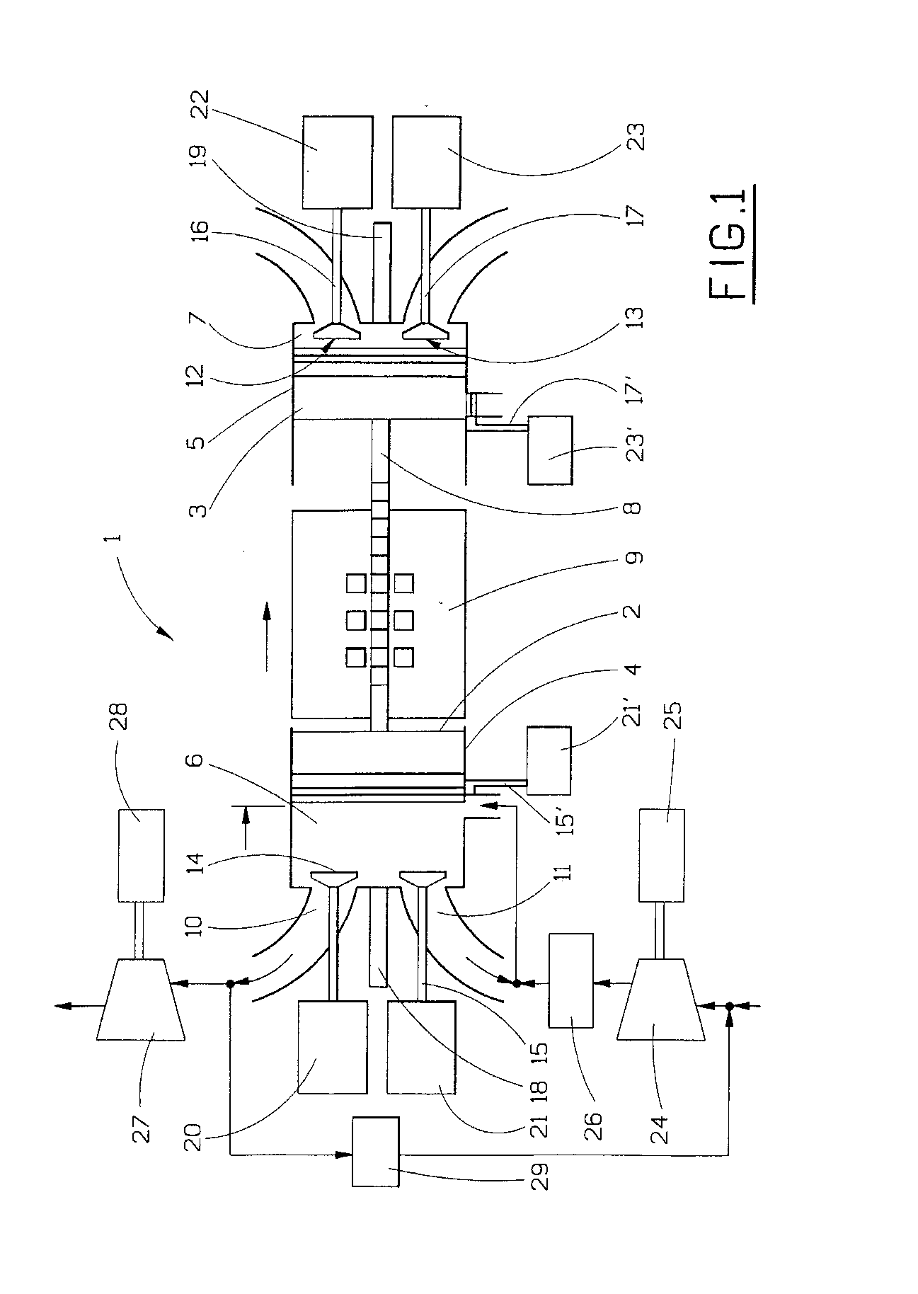
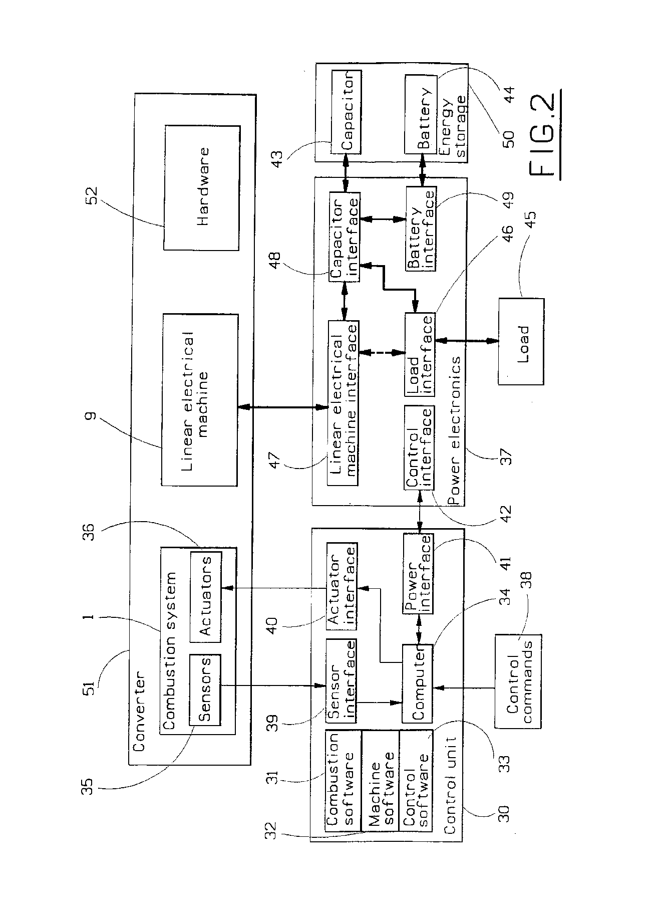
[0010] One object of the invention is to provide an energy converter that does not need large energy storage. In this regard, the invention is characterized by the fact that the energy converter is arranged to adapt its power output depending on the required load of the energy converter. By doing so, only small energy storage is needed. This reduces both the cost and the weight of the energy converter compared to previous solutions. Further, the invention can be operated very efficiently with very low fuel consumption and very low emissions.

Problems solved by technology

Although the existing free piston engine energy converters do convert chemical energy to electric energy in a fairly good way via combustion, they are driven in a constant load situation and therefore these solutions require large energy storage facilities such as battery packs.
This type of equipment is expensive and therefore lowers the efficiency of the system.

Method used


Image

  • Energy converter
  • Energy converter
  • Energy converter

Examples


Embodiment Construction

)

[0026] HCCI combustion: When a homogeneous, diluted (air or residual gas fraction) fuel / air mixture is compressed in an engine at such a high temperature that it auto-ignites, the engine is said to operate on homogeneous charge compression ignition.

[0027] Ignition points are provided by multiple exothermal centers (ETC) in the gas mixture. Since HCCI has no flame-propagation, the combustion is instead kinetically controlled. To generate multiple ETCs, it is important to be able to control the homogeneity of temperature and composition in the gas-mixture. The lack of flame-propagation causes the temperature distribution in the combustion chamber after combustion, in contrast to normal flame propagation, to be almost homogeneous. This leads to a reduction of NOx emissions from thousands of ppm to an order of ten ppm.

[0028] In the present context, kinetically controlled combustion means that the heat release can be extremely rapid which makes it theoretically possible to approach th...


PUM


Abstract

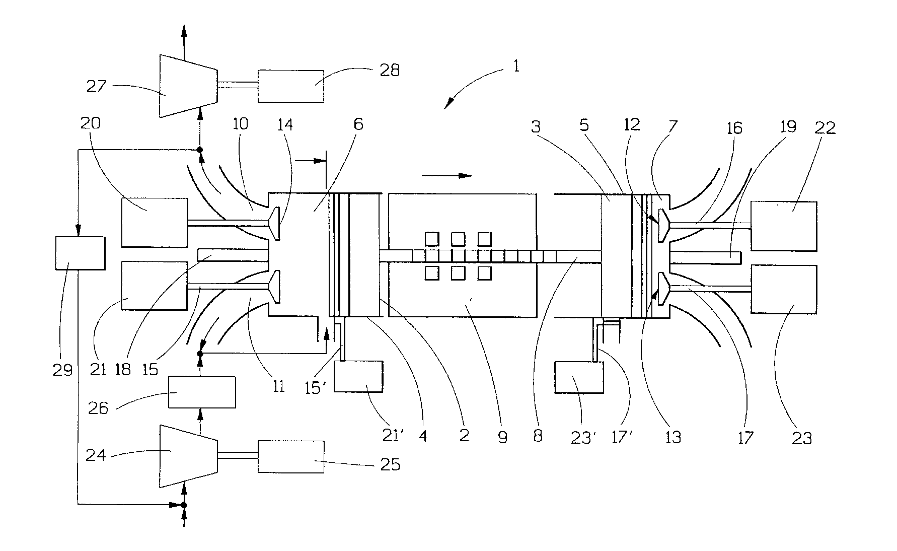
Method and arrangement for providing an energy converter that includes a combustion system ( 1 ) including at least one piston ( 2, 3 ), at least one combustion chamber ( 6, 7 ) having at least one inlet ( 11, 13 ) and at least one outlet ( 10, 12 ) with inlet and outlet valves ( 14, 15, 16, 17 ). At least one controllable inlet valve and at least one outlet valve is also provided. A fuel supply is provided ( 18, 19 ) for supplying fuel and a medium containing oxygen is provided for induction into the combustion chamber ( 6, 7 ). An electric machine ( 9 ) is arranged to interact directly or indirectly with the piston ( 2, 3 ) in an electromagnetic manner such that it produces electrical energy from the piston movements, as well as uses electrical energy to affect the piston movement. A control unit ( 30 ) controls the combustion system ( 1 ) and the electric machine ( 9 ). The energy converter is arranged to adapt its power output depending on the required load of the energy converter. The invention also relates to a method for for starting an energy converter.

Description

CROSS-REFERENCE TO RELATED APPLICATIONS [0001] The present application is a continuation patent application of International Application No. PCT / SE2003 / 001441 filed 15 Sep. 2003 which was published in English pursuant to Article 21(2) of the Patent Cooperation Treaty, and which claims priority to Swedish Application No. 0202758-9 filed 16 Sep. 2002. Said applications are expressly incorporated herein by reference in their entireties.TECHNICAL FIELD [0002] The present invention relates to an energy converter for a free piston engine having a fuel supply means and a medium containing oxygen for a combustion chamber of the engine. An electric machine is also included and which is arranged to interact with a piston of the engine in an electromagnetic manner so as to produce electrical energy from piston movements, as well as use electrical energy to affect the piston movements. A control unit (30) is also included that controls the engine and the electric machine. The invention also inc...

Claims


Application Information

Patent Timeline
IPC IPC(8): H02K33/00H02K35/00F02B71/00F01B11/00F01B23/10F02B1/12F02B37/00F02B71/02F02B71/04F02D13/02F02D29/06F02M25/07F02N11/02F02N11/04
CPCF02B1/12F02B37/00F02B63/041F02B71/02F02B71/04F02D13/0215Y02T10/18F02D29/06F02M25/0752F02N11/02F02N11/04Y02T10/121F02D13/0265F02M26/01
Inventor MAX, ERLANDLUNDGREN, STAFFANSOMHURST, JOOPHOGLUND, ANDERSWIRMARK, GORANGERTMAR, LARSDENBRATT, INGEMAR
Owner VOLVO CAR CORP
Learn More