
Visco Elastic Damping In A Piping System

a technology of viscoelasticity and piping system, which is applied in the direction of flexible pipes, pipe supports, pipe elements, etc., can solve the problems of affecting piping systems that are susceptible to rupture, leakage and subsequent risk of explosion, and problems such as serious dimensions, to achieve the effect of damping vibrations

Inactive Publication Date: 2008-02-14
INGEMANSSON TECH +1
View PDF8 Cites 13 Cited by
  • Summary
  • Abstract
  • Description
  • Claims
  • Application Information

AI Technical Summary

Benefits of technology

[0011] One main object of the present invention is to provide a piping system for visco elastic damping which in a practical and effective way substantially counteracts the internal loads, such as flow induced pressure variations, in the piping system, in order to among other things increase the safety.
[0017] A fundamental idea of the present invention is to damp oscillations of a pipe or pipe detail(s) in a piping system by means of one or more autonomous, i.e. self-damping, visco elastic dampers or damper links by connecting two different parts of the piping system with each other and / or between the piping system or structure and another free standing object, such as a supporting structure, via one or more of said dampers or damper links, which dampers or damper links are stiffly attached to the pipe or pipe detail(s) to be damped and the piping structure. Thus, the damping of the pipe or pipe detail(s) substantially limit the relative displacements between the two different parts of the piping system, thereby limiting the oscillating material strain which is what causes fatigue failure.
[0019] The use of discrete damping elements makes it possible to increase, structural damping of oscillations in piping systems for liquids and gases locally to individual parts or sections of the system. The discrete dampers may be regarded as components attached between two substructures, which can be structurally connected to other neighbouring surfaces. The active parts of the visco elastic dampers will transform a substantial amount of the vibration-deformation energy into heat during the course of each vibration or oscillation cycle and thereby damping the vibrations. The present invention solves the above-mentioned types of oscillation problems in piping systems through the targeted introduction of a practical form of structural damping, instead of modifying the stiffness and / or inertia of the system as in the prior art.

Problems solved by technology

The problem may rise to serious dimensions if the pipes and associated pipe and structural details have natural frequencies which coincide with the excitation frequency in such a way that resonance arises.
Such types of resonance have in some cases caused ruptures in the affected piping systems with leakage and subsequent risk of explosions as a consequence.
Attempts to solve the problem by adding additional stiffening components have little effect, as such stiffening only changes the natural frequencies of the system and does not remove either the excitation or the response energy.
As the excitation spectrum is relatively broad with typical values from above 50 Hz and multiples thereof, and the base excitation frequency varies with pressure and speed, it is extremely difficult to significantly improve the situation by the use of stiffening components alone.
Metal piping systems have therefore little natural damping, which is partly the reason that resonance becomes a problem.
Traditional dampers, such as mass dampers, snubbers, hydraulic dampers, plasma dampers and “Gerb”-dampers, do not function well at the type of load in question, namely high frequency, broad frequency spectra and small amplitudes.
A possible method of damping oscillations is visco elastic damping, but there is hitherto no known method for applying this form of damping to piping systems which are located in an environment with temperature variations beyond the working range of the visco elastic material and in which the vibrations have very small amplitudes.
The latter has the consequence that it is difficult to achieve the necessary deformation in the damping material.

Method used


Image

  • Visco Elastic Damping In A Piping System
  • Visco Elastic Damping In A Piping System
  • Visco Elastic Damping In A Piping System

Examples


Embodiment Construction

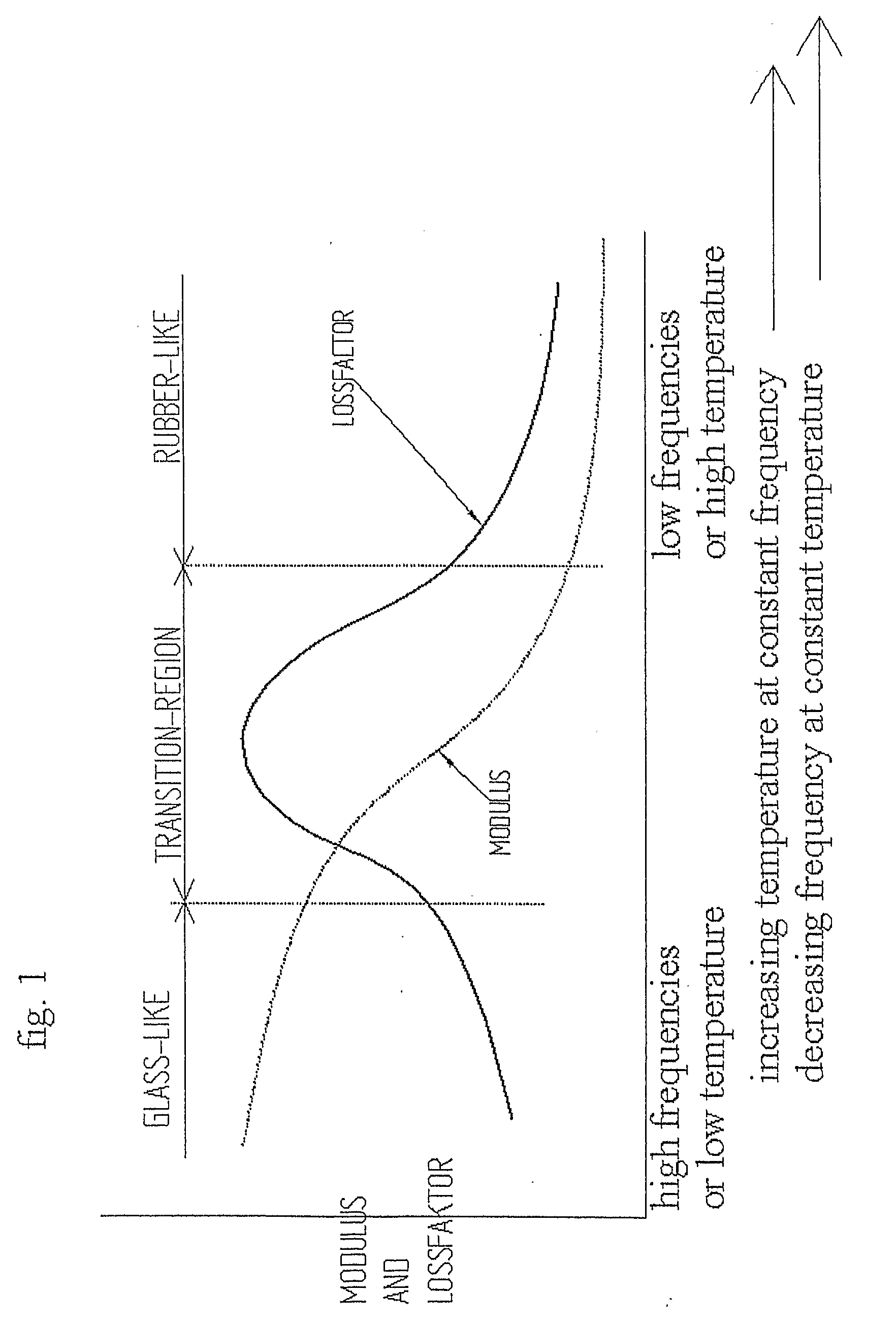
[0037]FIG. 1 shows how the modulus of elasticity and loss factor for a visco elastic material vary both as a function of increasing surrounding temperature when vibration frequency is held constant and decreasing vibration frequency when surrounding temperature is held constant, with the visco elastic materials working temperature given as the temperature range between glass-like and rubber-like behaviour states.

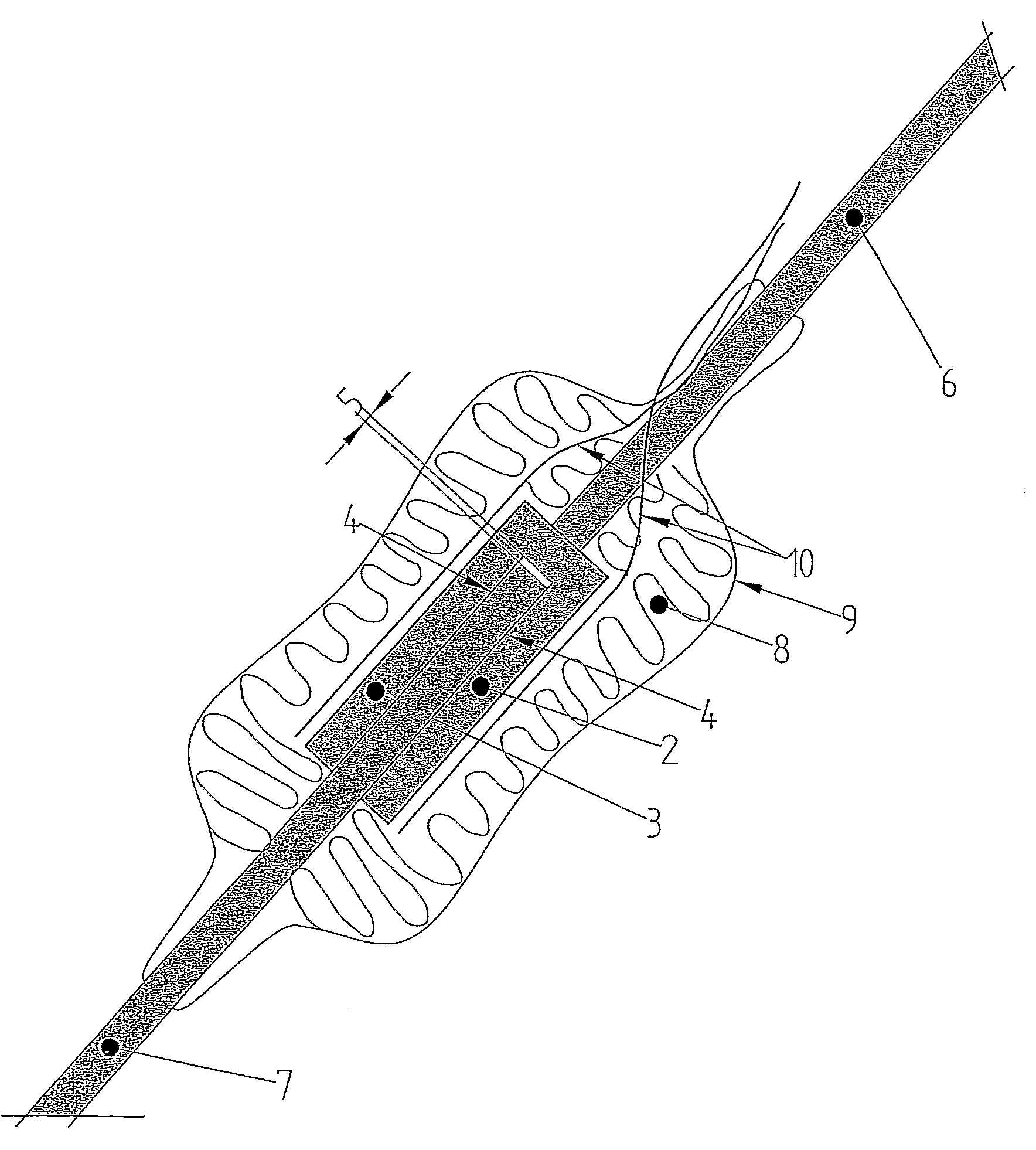
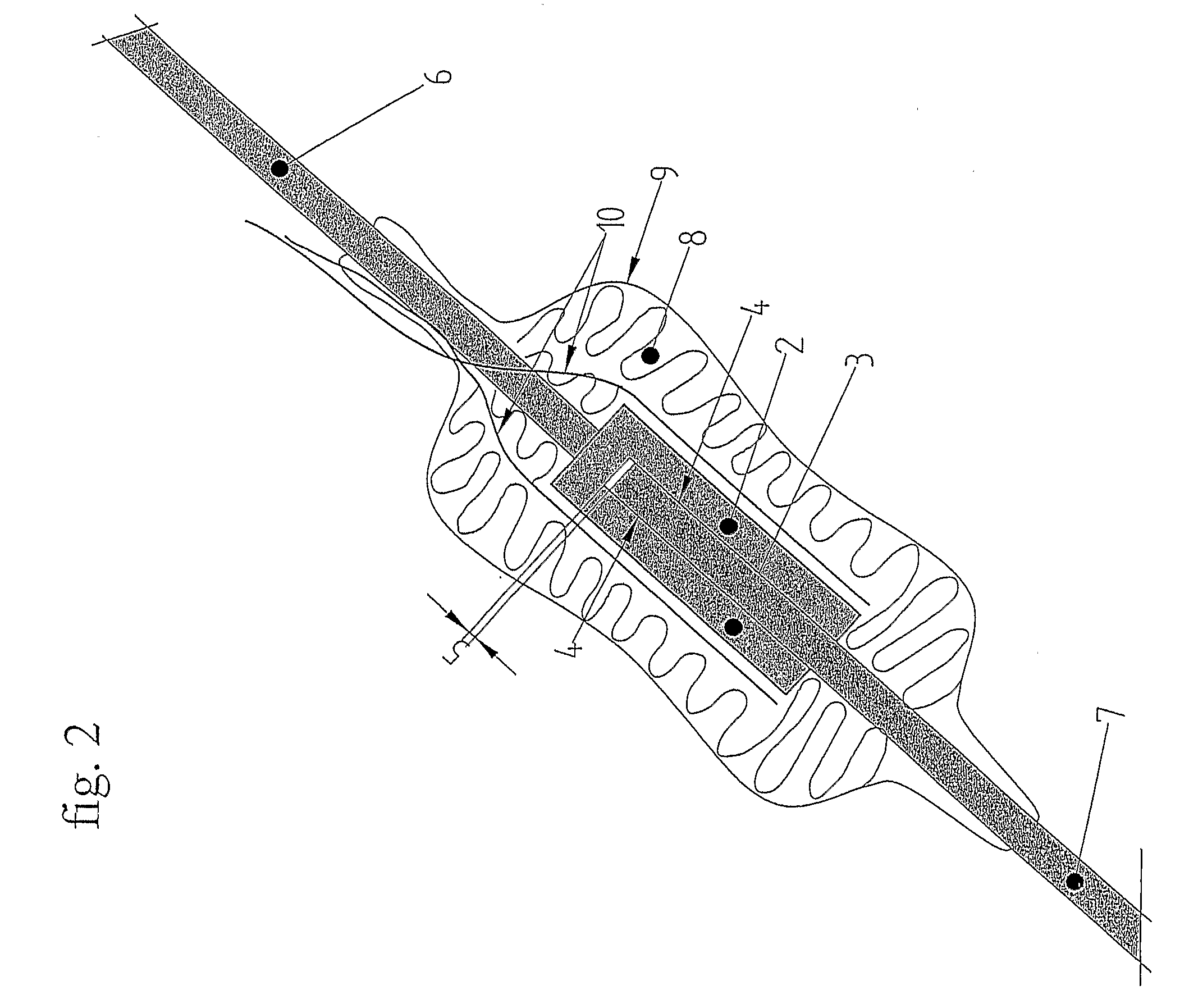
[0038]FIG. 2 shows a schematic cross section of a visco elastic damper in a cross section, which damper constitutes a damper link connected between two different parts of a piping system and / or between the piping system and another free standing object. The damper link comprises a first stiff member comprising two spaced-apart stiff plate elements 2 and 3 forming a U-shape cross section, and an end part of a strut 6 or the like connected thereto so as to form a flat fork-like (flat yoke) structure at the one end, and a second stiff member in the form of an end part of a fla...


PUM


Abstract

A piping system for visco elastic damping, which system oscillates with high frequency, small amplitude oscillations. The system includes one or more autonomous visco elastic dampers that includes one or more layers of visco elastic damping material fixedly bonded between stiff members. The visco elastic dampers may be provided with a temperature controlling element.

Description

FIELD OF THE INVENTION AND PRIOR ART [0001] The present invention relates to a piping system for visco elastic damping, which system oscillates with high frequency, small amplitude oscillations. [0002] In particular, the invention has been developed in connection with the growing problem of acoustic oscillations in piping structures or systems used for transport of fluids. The problem may rise to serious dimensions if the pipes and associated pipe and structural details have natural frequencies which coincide with the excitation frequency in such a way that resonance arises. Additional amplification may arise if the natural frequency of the pipes and associated pipe and structural details, such as support arrangements, attached valves and measuring devices etc., coincides with acoustic natural frequencies such that fluid-structure interaction occurs. Such types of resonance have in some cases caused ruptures in the affected piping systems with leakage and subsequent risk of explosio...

Claims


Application Information

Patent Timeline
Patent Type & Authority Applications(United States)
IPC IPC(8): F16L55/02F16FF16F9/30F16F13/00F16L3/16F16L55/035
CPCF16F9/30F16L55/035F16L3/16
Inventor FREDO, CLAESWIGAARD, JAN
Owner INGEMANSSON TECH
Learn More