Refrigerant circuit system

a circuit system and refrigeration technology, applied in refrigeration components, transportation and packaging, light and heating apparatus, etc., can solve the problems of increased labor and material costs, and achieve the effect of maximizing efficiency and minimizing costs and difficulties in manufacturing and assembly

Inactive Publication Date: 2008-02-14
VISTEON GLOBAL TECH INC
View PDF2 Cites 4 Cited by
  • Summary
  • Abstract
  • Description
  • Claims
  • Application Information

AI Technical Summary

Benefits of technology

[0007]Harmonious with the present invention, a refrigerant circuit system for use in vehicle HVACs, wherein a cost and difficulty of manufacture and assembly thereof are minimized, and an efficiency thereof is maximized, has surprisingly been discovered.
[0010]In another embodiment, a refrigerant circuit system comprises a compressor; a gas cooler in fluid communication with the compressor; a combined component in fluid communication with the compressor and the gas cooler, the combined component including an internal heat exchanger and an accumulator, the internal heat exchanger including a high-pressure entrance and a pair of high pressure exits, the accumulator including a pair of low pressure entrances and a low pressure exit; a refrigerant line for interconnecting the gas cooler to the compressor, the gas cooler to the combined component, and the combined component to the compressor; a pair of branches including an evaporator and an expansion member, wherein one of the branches is in fluid communication with one of the high pressure exits of the internal heat exchanger and one of the low pressure entrances of the accumulator and the other of the branches is in fluid communication with the other of the high pressure exits of the internal heat exchanger and the other of the low pressure entrances of the accumulator, and wherein the evaporators are disposed downstream of the expansion members, and the pair of branches form a parallel circuit from the combined component; and a manifold disposed on the combined component, wherein the manifold facilitates communication between the combined component and the pair of branches, the manifold including a first double connection element that facilitates communication between the manifold and the expansion member and manifold and the evaporator in one of the branches, and a second double connection element that facilitates communication between the manifold and the expansion member and the manifold and the evaporator in the other one of the branches.
[0014]In one embodiment, the manifold is equipped with double connection elements, which allows a minimization of the number of screwing points and simplifies the interconnection of the lines, resulting in a more clearly arranged line design.
[0018]Typically, either one or two screws are required for fastening a double connection element which save time-intensive screwing operations.
[0019]Compared to prior art, the solution according to this invention facilitates a cost-effective and time-effective manufacture process.

Problems solved by technology

Thus, the increased number of screwing points and growing interconnection of the lines not only results in increased effort during manufacture, but also raised material costs.

Method used


Image

  • Refrigerant circuit system
  • Refrigerant circuit system
  • Refrigerant circuit system

Examples


Embodiment Construction

[0029]The following detailed description and appended drawings describe and illustrate various exemplary embodiments of the invention. The description and drawings serve to enable one skilled in the art to make and use the invention, and are not intended to limit the scope of the invention in any manner.

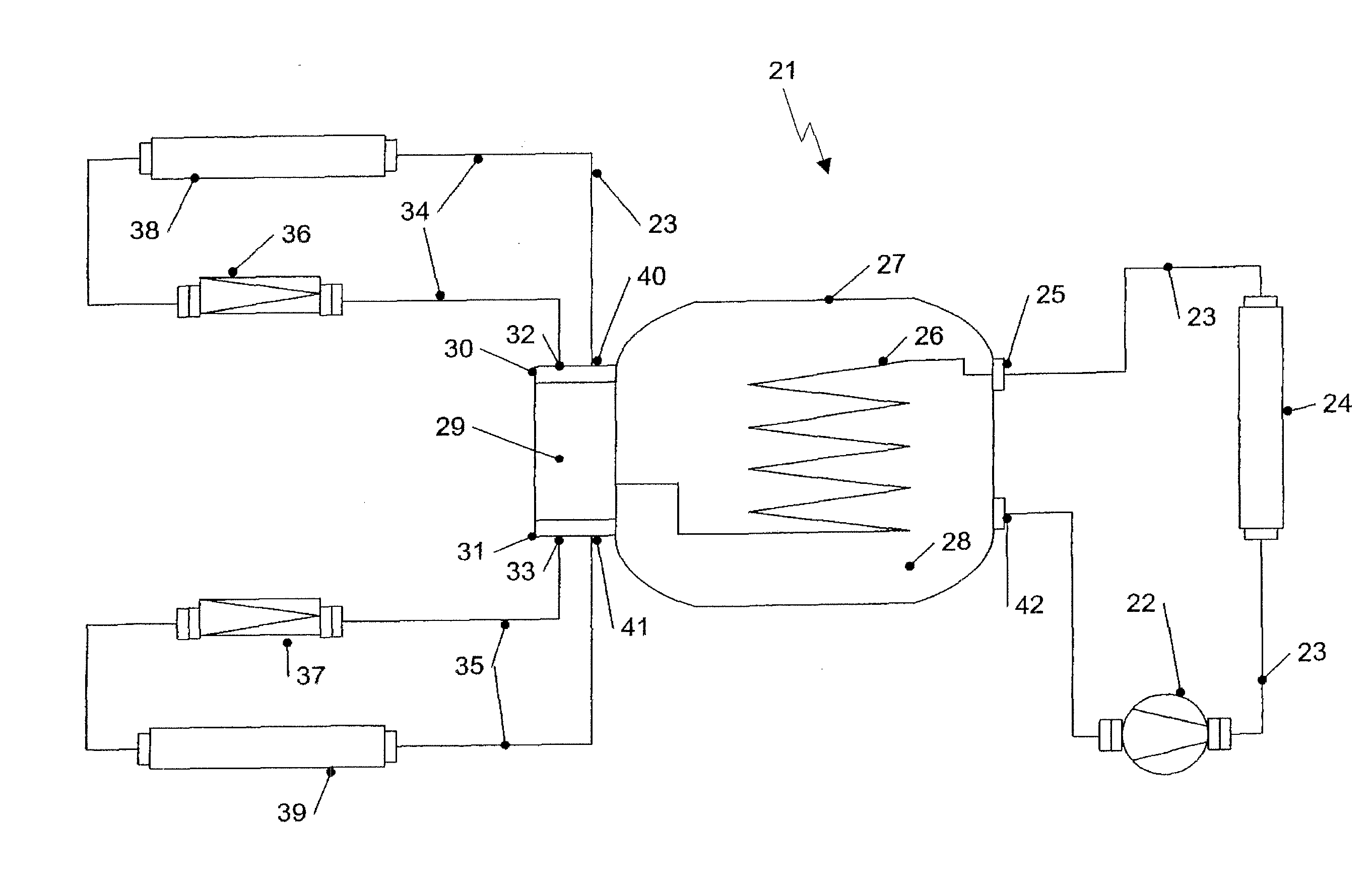
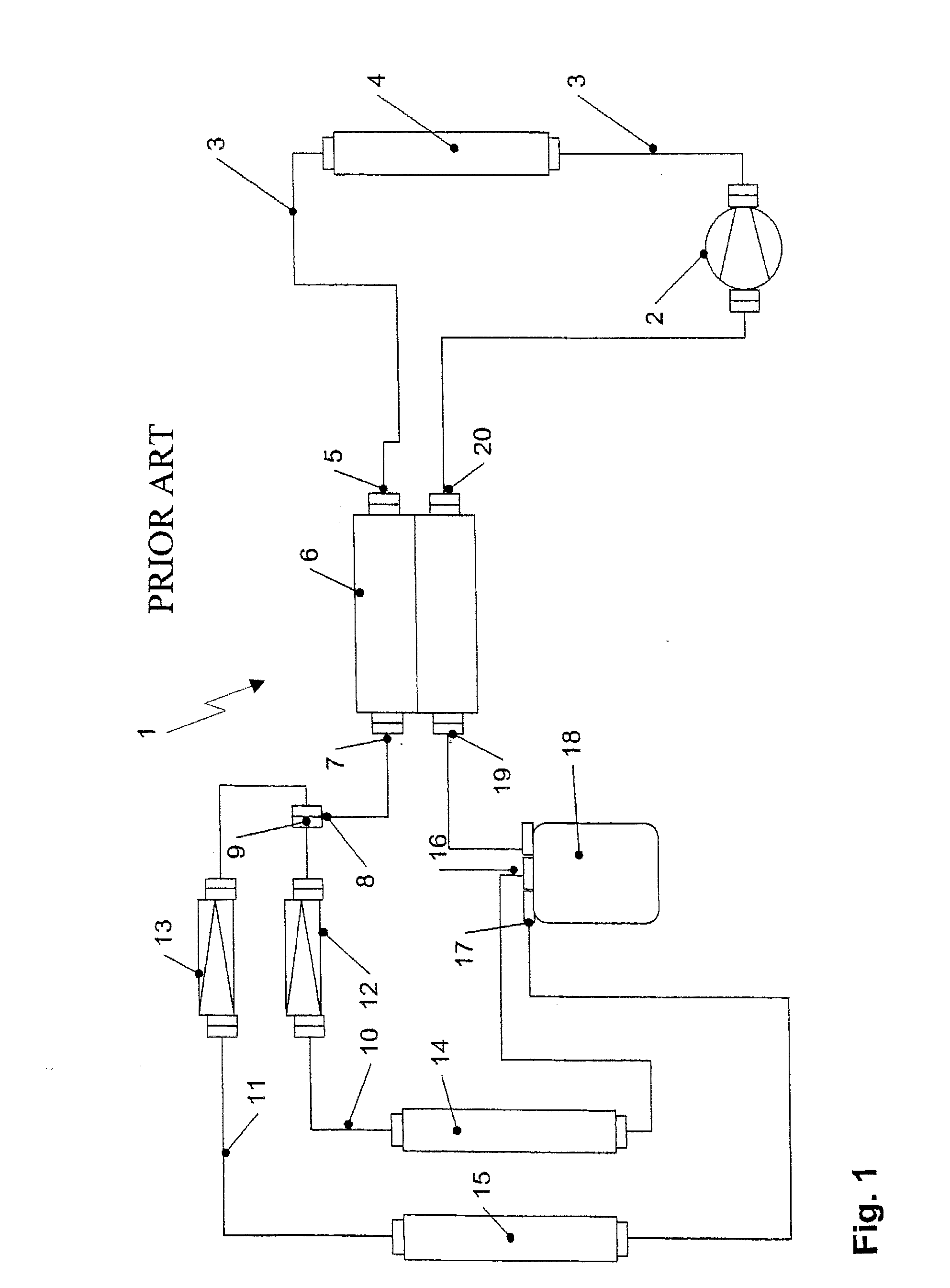
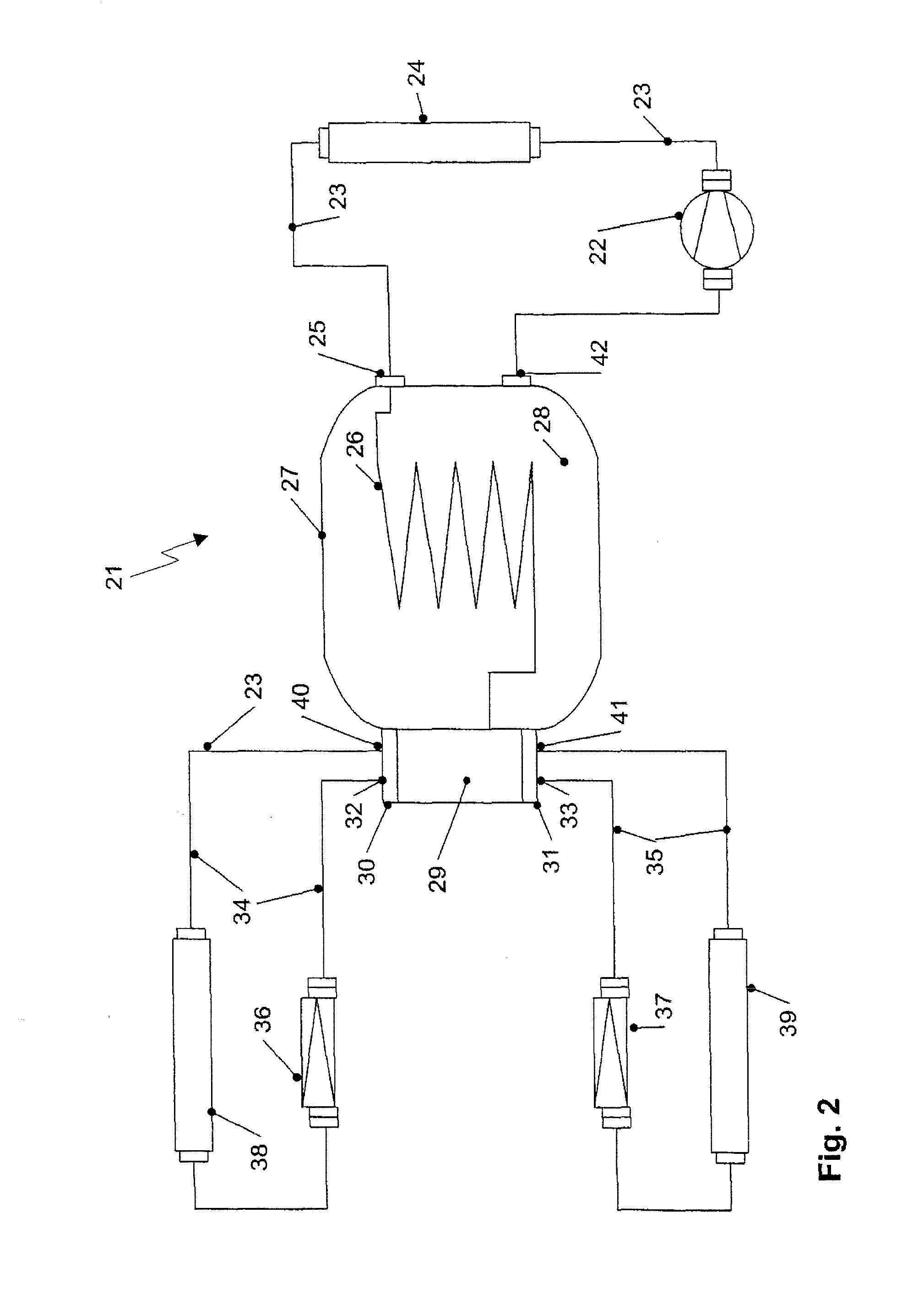
[0030]The block diagram of FIG. 1 shows a prior art HVAC usable to condition air in a vehicle. Such an HVAC has a refrigerant circuit system 1 employing a suitable refrigerant. From a compressor 2 the refrigerant flows through the refrigerant line 3 on the high-pressure side to a gas cooler 4, where the refrigerant is cooled by an environmental air flow. Then the refrigerant flows over the high-pressure entrance 5 into the internal heat exchanger 6 and after having passed the internal heat exchanger 6, over a high-pressure exit 7 to a manifold connection 8. The manifold connection 8 is placed on the refrigerant line 3, whereby the manifold 9 established as three-way screwing point di...


PUM


Abstract

A refrigerant circuit for a vehicle heating, ventilation, and air conditioning system is disclosed, wherein the refrigerant circuit includes a combined component including an internal heat exchanger and an accumulator, and wherein a cost and difficulty of manufacture and assembly thereof are minimized, and an efficiency thereof is maximized.

Description

CROSS-REFERENCE TO RELATED APPLICATION[0001]This application claims the benefit of German Patent Application No. 102006038728.7 REFRIGERANT CIRCUIT SYSTEM filed on Aug. 11, 2006, hereby incorporated herein by reference in its entirety.FIELD OF THE INVENTION[0002]The invention generally relates to a refrigerant circuit system and more particularly, to a refrigerant circuit system for a vehicle heating, ventilation, and air conditioning system (HVAC).BACKGROUND OF THE INVENTION[0003]Refrigerant circuit systems that employ CO2, as a refrigerant are particularly used in motor vehicle HVACs. Refrigerant circuit systems are provided with a compressor for compressing the gas and a gas cooler for cooling the gas discharged by the compressor. After the gas has been cooled down in the gas cooler, it flows into an internal heat exchanger. The internal heat exchanger functions to transfer heat within the system for supercooling from the high-pressure side to the low-pressure side, which is ther...

Claims


Application Information

Patent Timeline
IPC IPC(8): F25B5/02
CPCB60H1/323F25B5/02F25B40/00F25B43/006F28F9/0246F25B2400/051F25B2500/18F25B2600/2511F25B2309/061
Inventor KLOTTEN, THOMASPRINZ, DOMINIK
Owner VISTEON GLOBAL TECH INC
Why Eureka
Try Eureka