Hydraulic rotary motor

a rotary motor and rotary motor technology, applied in the direction of rotary or oscillating piston engines, rotary piston engines, engine lubrication, etc., can solve the problems of large axial construction length of motors and relatively high production and assembly effort, and achieve the effect of small

Inactive Publication Date: 2008-02-07
KINSHOFER
View PDF2 Cites 2 Cited by
  • Summary
  • Abstract
  • Description
  • Claims
  • Application Information

AI Technical Summary

Benefits of technology

[0025]An oil guiding system or passage system is advantageously also provided for the lubrication of the ring piston for this. To transport the oil onto the axial surfaces of the ring piston, the ring piston thickness can reduce toward the edges of the outer toothed arrangement, with bevels, for example in the form of a chamfer toward the outer meshing noses, in particular being provided at the rims of the axial plain bearing surfaces of the ring piston. This facilitates the oil being able to move onto the plain bearing surfaces of the ring piston. The outwardly conical shape of the piston moreover ensures a flooding and centering of the ring piston. Furthermore, the parallelism and angle defects have a smaller effect.

Problems solved by technology

However, what is disadvantageous with this support of the motor shaft via tapered roller bearings is, however, the large axial construction length of the motor which hereby arises.
In addition, the production and assembly effort is relatively high due to the corresponding components.

Method used


Image

  • Hydraulic rotary motor
  • Hydraulic rotary motor
  • Hydraulic rotary motor

Examples


Embodiment Construction

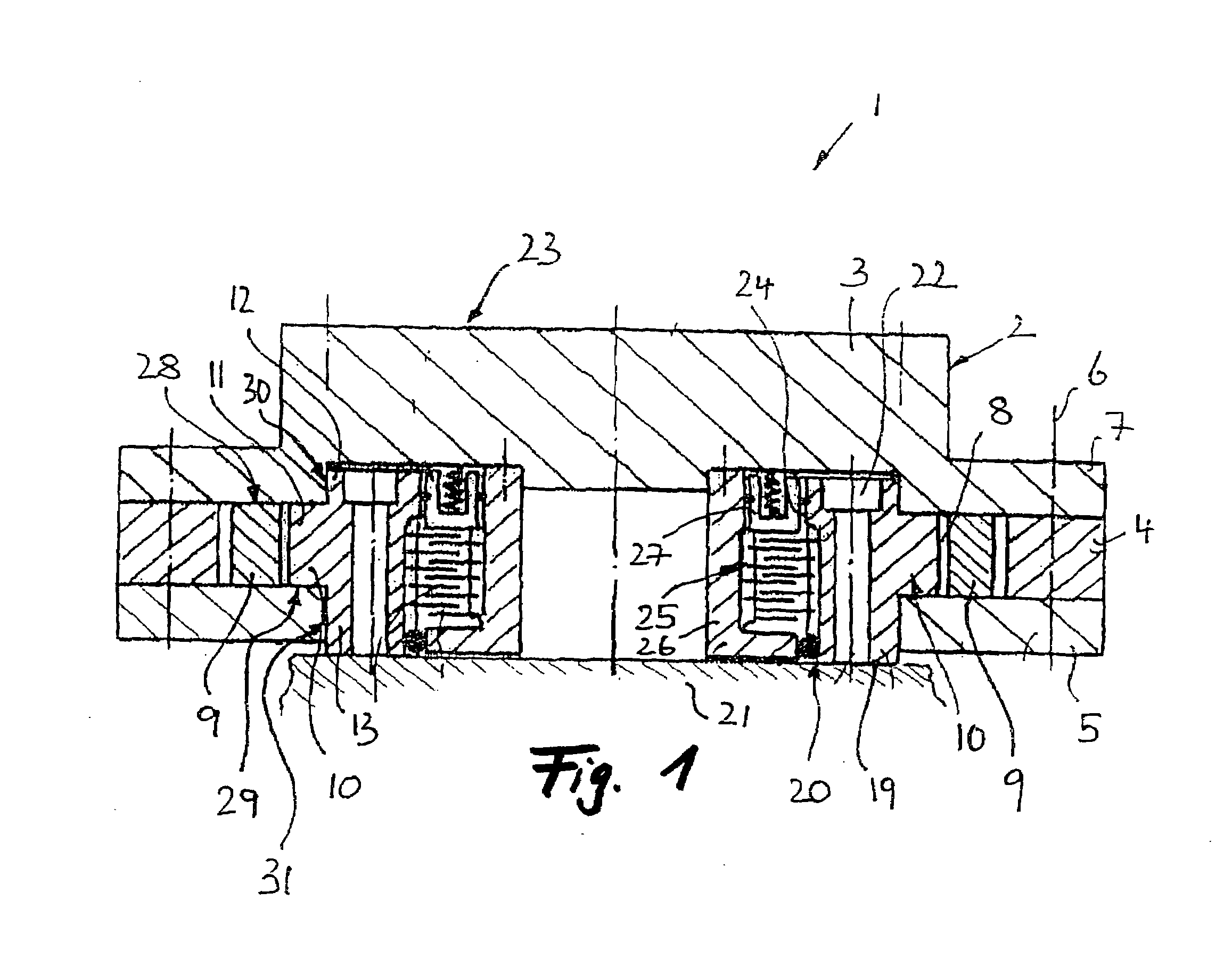
[0043]The rotary motor 1 shown in FIG. 1 comprises a substantially cup-shaped housing 2 which consists in the drawn embodiment substantially of three parts, namely the motor head 3, the rotor housing ring 4 and the bearing cover 5. As FIG. 1 shows, the bearing cover 5 is set on the rotor housing ring 4 and is screwed via screw connections 6 to the radially projecting flange 7 of the motor head 3 so that an annular rotor gap 8 is formed between the bearing cover 5 and the motor head 3. The ring piston 9 is received in the said rotor gap 8 as is—radially inside this ring piston 9—the substantially likewise disk-shaped rotor 10. In more precise terms, a disk section 11 of a rotor / shaft unit is seated with an exact fit between the bearing cover 5 and the motor head 3. Shaft sections 12 and 13 are shaped in a projecting manner at both sides of the disk section 11 and their outer periphery runs with an exact fit on inner peripheral surfaces of the bearing cover 5 or of the motor head 3.

[0...


PUM


Abstract

A hydraulic rotary motor, in particular to a stewing gear for elevating plant such as excavator grabs, etc., comprising a housing in which a rotor is rotatably received as well as a ring piston having an inner toothed arrangement and an outer toothed arrangement which is seated between the rotor and the housing so that displacement chambers are formed between the ring piston and an outer toothed arrangement of the rotor and/or an inner toothed arrangement of the housing, with a first motor connector being rotatably fixedly connected to the housing and a second motor connector being rotatably fixedly connected to the rotor. The hydraulic rotary motor is characterized in that the rotor is axially and radially supported at the housing via plain bearings and the second motor connector connected to the rotor is solely supported via the plain bearings at the housing.

Description

BACKGROUND OF THE INVENTION[0001]1. Field of the Invention[0002]The present invention relates to a hydraulic rotary motor, in particular to a slewing gear for elevating plant such as excavator grabs, etc., comprising a housing in which a rotor is rotatably received as well as a ring piston having an inner toothed arrangement and an outer toothed arrangement which is seated between the rotor and the housing so that displacement chambers which can be filled with pressure fluid are formed between the ring piston and an outer toothed arrangement of the rotor and / or an inner toothed arrangement of the housing, with a first motor connector being rotatably fixedly connected to the housing and a second motor connector being rotatably fixedly connected to the rotor.[0003]2. Description of the Prior Art[0004]Such a hydraulic rotary motor is known from DE 33 42 131 A1. DE 37 29 049 C1, DE 2 365 057 or DE 196 05 879 A1 also show hydraulic rotary motors of this type in which a ring piston orbits...

Claims


Application Information

Patent Timeline
Patent Type & Authority Applications(United States)
IPC IPC(8): F01C1/02F01C1/063
CPCF03C2/08F04C2/10F04C15/0088F04C15/0084F04C15/0038
Inventor FRIEDRICH, THOMAS
Owner KINSHOFER
Why Eureka
Try Eureka