
Display drive apparatus and display apparatus

a technology of display apparatus and drive apparatus, which is applied in the direction of instruments, measurement devices, computing, etc., can solve problems such as the quality of displayed images deteriorating

Active Publication Date: 2008-02-07
SOLAS OLED LTD
View PDF18 Cites 47 Cited by
  • Summary
  • Abstract
  • Description
  • Claims
  • Application Information

AI Technical Summary

Benefits of technology

[0010]The present invention is advantageous in that a display drive apparatus which drives a display pixel including light-emitting elements and a display apparatus including the display drive apparatus can suppressed from causing an insufficient writing and can compensate a variation in characteristics of a drive element of a display pixel to allow the light-emitting elements to emit, for a long period of time, light with brightness suitable for a luminance gradation of display data.

Problems solved by technology

However, the current-writing method may cause a case where, when gradation current in accordance with display data having the lowest or relatively-low brightness is written to the respective display pixels, a writing time constant causes an increased time for charging a data line to cause a longer writing operation to prevent a previously-set writing time from providing a sufficient writing operation to cause a so-called insufficient writing to cause a deteriorated quality of a displayed image.
However, variation in characteristics of a switching element of a pixel drive circuit causes variation in a value of current flowing during a writing operation to cause variation in a voltage component held by a pixel drive circuit to cause variation in a value of a drive current flowing through a light-emitting element.

Method used


Image

  • Display drive apparatus and display apparatus
  • Display drive apparatus and display apparatus
  • Display drive apparatus and display apparatus

Examples


Embodiment Construction

[0076]Hereinafter, a display drive apparatus and the drive method thereof according to the present invention as well as a display apparatus and the drive method thereof will be described based on embodiments shown in the drawings.

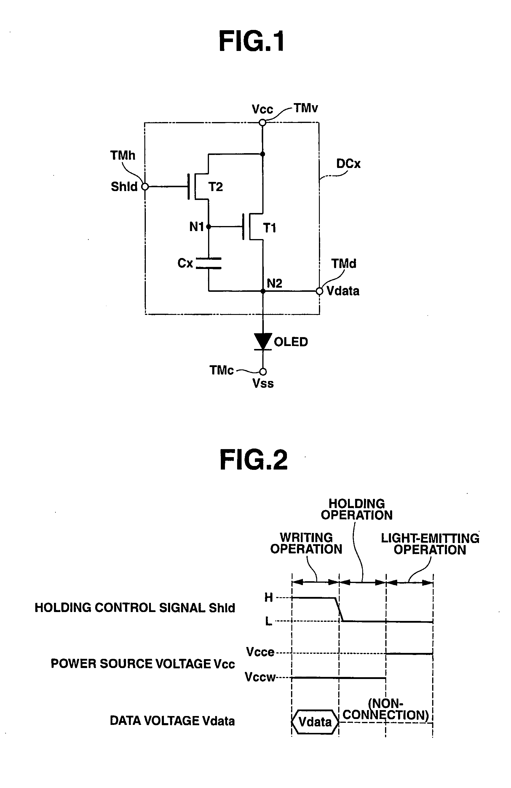
[0077]First, the main structure and the control operation of a display pixel used in a display apparatus according to the present invention will be described with reference to the drawings.

[0078]FIG. 1 is an equivalent circuit diagram illustrating the main structure of a display pixel used in a display apparatus according to the present invention.

[0079]The following section will describe a case where an organic EL element is conveniently used as a current control-type light-emitting element provided in a display pixel.

[0080]A display pixel used in a display apparatus according to the present invention has a circuit structure as shown in FIG. 1 that comprises a pixel drive circuit DCx and an organic EL element OLED as a current control-type light-emitting el...


PUM


Abstract

A display pixel including a light-emitting element and a drive element for supplying current flowing in a current path to the light-emitting element is applied with a detection voltage based on a predetermined unit voltage. Based on a value of current flowing in the current path of the drive element, a specific value corresponding to an element characteristic of the drive element is detected. A gradation voltage corresponding to a luminance gradation of display data is generated. Based on the specific value and the unit voltage, a compensated voltagea is generated. By compensating the gradation voltage based on the compensated voltage, a compensated gradation voltage is generated. And the compensated gradation voltage is supplied to the display pixel.

Description

BACKGROUND OF THE INVENTION[0001]1. Field of the Invention[0002]The present invention relates to a display drive apparatus and a drive method thereof, and a display apparatus and the drive method thereof. In particular, the present invention relates to a display drive apparatus for drive a display pixel including a light-emitting element that emits light by receiving current, and a display apparatus including a display panel in which the display pixels are arranged in a plurality of rows that display image information and the drive method thereof.[0003]2. Description of the Related Art[0004]In recent years, a self light emitting-type display apparatus has been actively researched and developed as a next-generation display device following a liquid crystal display apparatus. A self light emitting-type display apparatus includes a display panel in which organic electroluminescence elements (organic EL elements), inorganic electroluminescence elements (inorganic EL elements), or elemen...

Claims


Application Information

Patent Timeline
Patent Type & Authority Applications(United States)
IPC IPC(8): G09G5/00G09G3/30
CPCG09G3/3233G09G3/3291G09G2300/0842G09G2320/043G09G2300/0866G09G2320/0295G09G2300/0847G09G3/30G09G3/32G09G3/20G01R19/00
Inventor SHIRASAKI, TOMOYUKIOGURA, JUN
Owner SOLAS OLED LTD
Learn More