
Non-volatile storage device, data storage system, and data storage method

a non-volatile memory and storage device technology, applied in the direction of memory architecture accessing/allocation, instruments, computing, etc., can solve the problems of poor efficiency, waste of resources, and long time-consuming garbage collection process

Inactive Publication Date: 2008-01-31
PANASONIC CORP
View PDF8 Cites 51 Cited by
  • Summary
  • Abstract
  • Description
  • Claims
  • Application Information

AI Technical Summary

Benefits of technology

"The present invention provides a non-volatile storage device that allows for high-speed data writing. The device includes a non-volatile memory and a memory controller for writing data into the non-volatile memory. The memory controller has two sections for holding data: a first section and a second section. The first section holds data that is input from the outside of the device and is temporarily stored in a temporary storage means before being written into the non-volatile memory. The second section holds data that is input from the outside of the device and is written into the non-volatile memory. The second section can only hold a limited amount of data, so a portion of the data is written into the non-volatile memory and the rest of the data is written into a second temporary storage means before being written into the non-volatile memory. This reduces the time required for data transfer and ensures high efficiency in writing data to the non-volatile memory."

Problems solved by technology

However, in the external storage system of Japanese Unexamined Patent Application Publication No. 5-27924, the garbage collection process requires a relatively long time.
In this case, consequently, the number of times of writing is plural in order to write the predetermined page of data into the non-volatile memory, so that it takes a long time to write data into the non-volatile memory, resulting in poor efficiency.
However, the cost of the device is increased with an increase in the capacity of the memory.

Method used


Image

  • Non-volatile storage device, data storage system, and data storage method
  • Non-volatile storage device, data storage system, and data storage method
  • Non-volatile storage device, data storage system, and data storage method

Examples


embodiment 1

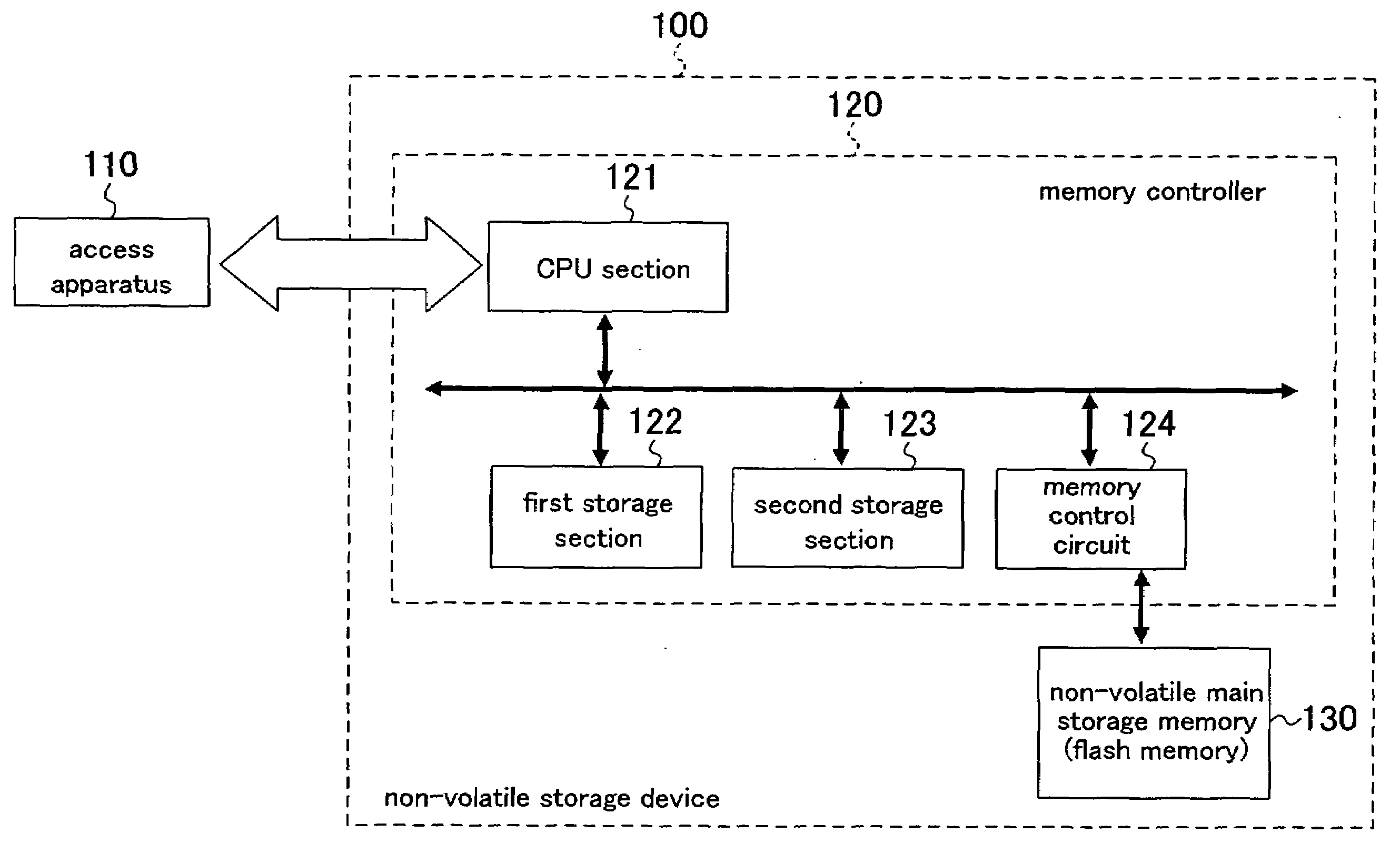
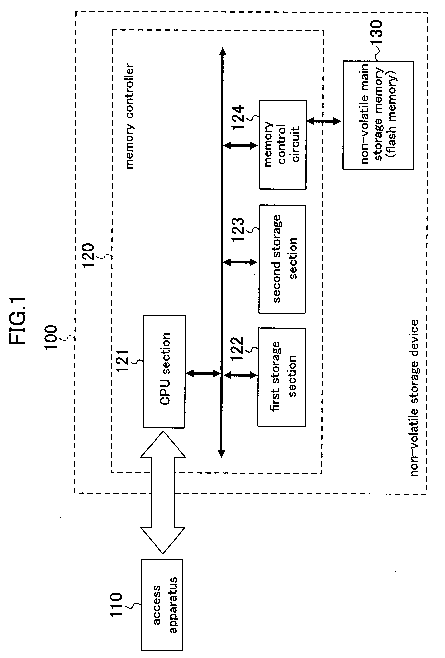
[0064]FIG. 1 is a block diagram illustrating a configuration of a data storage system according to Embodiment 1 of the present invention. The data storage system comprises a non-volatile storage device 100 and an access apparatus 110. The non-volatile storage device 100 is connected to the access apparatus 110.

[0065]As illustrated in FIG. 1, the non-volatile storage device 100 comprises a memory controller 120 and a non-volatile memory 130 including a flash memory.

[0066]The access apparatus 110 is provided external to the non-volatile storage device 100 and accesses the non-volatile storage device 100. More specifically, the access apparatus 110 transmits a command to read or write user data (hereinafter referred to as “data”), transmits a logical address at which the data is stored, and transmits and receives data via the memory controller 120 to or from the non-volatile memory 130. The access apparatus 110 is a main computer, an in-vehicle terminal, or the like.

[0067]The memory co...

embodiment 2

[0122]A non-volatile storage device 100 according to Embodiment 2 of the present invention has the same basic configuration as that of the non-volatile storage device 100 of Embodiment 1, except for the operation.

[0123]Hereinafter, an operation of the non-volatile storage device 100 of Embodiment 2 of the present invention will be described with reference to FIG. 7.

[0124](S700) The non-volatile storage device 100 goes to a state in which it waits for a data write command (hereinafter referred to as a WCMD) from the access apparatus 110. When receiving the WCMD from the access apparatus 110, the non-volatile storage device 100 goes to a process of (S701).

[0125](S701) When a sector of data and the logical address of the data are transferred (transmitted) from the access apparatus 110, the CPU section 121 stores a value of the transferred logical address into a register of the CPU section 121, and writes the data into the first storage section 122.

[0126](S702) The CPU section 121 deter...

embodiment 3

[0154]A non-volatile storage device 100 according to Embodiment 3 of the present invention has the same basic configuration as that of the non-volatile storage device 100 of Embodiment 1, except for the operation.

[0155]Also, the non-volatile storage device 100 of this embodiment comprises an address history management section in the CPU section 121. The address history management section stores a history of logical addresses externally input to the non-volatile storage device 100.

[0156]The operation of the non-volatile storage device 100 of this embodiment is different from that of the non-volatile storage device 100 of Embodiment 1 in that processes of (S1000) to (S1007) of FIG. 10 are executed instead of the processes of (S400) to (S406) of FIG. 4.

[0157]Hereinafter, an operation of the non-volatile storage device 100 of Embodiment 3 of the present invention will be described with reference to FIG. 10.

[0158](S1000) The non-volatile storage device 100 goes to a state in which it wai...


PUM


Abstract

A non-volatile storage device comprises a non-volatile memory into which data is written per unit area, and a memory controller for controlling writing of data into the non-volatile memory. The memory controller comprises a first storage section for holding data input from the outside of the device, a first control section for writing data which is held by the first storage section and whose amount corresponds to the unit area, into the non-volatile memory in a unit area-by-unit area basis, and writing data which is held by the first storage section and whose amount is less than the unit area, into a second storage section, and a second control section for writing data held by the second storage section into the non-volatile memory.

Description

CROSS REFERENCE TO RELATED APPLICATION[0001]This Non-provisional application claims priority under 35 U.S.C. §119(a) on Patent Application No. 2006-208552 filed in Japan on Jul. 31, 2006, the entire contents of which are hereby incorporated by reference.BACKGROUND OF THE INVENTION[0002]1. Field of the Invention[0003]The present invention relates to a non-volatile storage device comprising a rewriteable non-volatile memory, a data storage system comprising the non-volatile storage device, and a data storage method for writing data into the non-volatile memory.[0004]2. Description of the Related Art[0005]There is an increasing demand for non-volatile storage devices comprising rewriteable non-volatile main storage memories, such as, mainly, semiconductor memory cards. There are various types of semiconductor memory cards, including, for example, SD memory cards (registered trademark). The SD memory card comprises a flash memory as a non-volatile main storage memory, and also has a mem...

Claims


Application Information

Patent Timeline
Patent Type & Authority Applications(United States)
IPC IPC(8): G06F12/00
CPCG06F12/0246G06F12/0804G11C16/10G06F2212/7203G06F13/1668
Inventor MATSUURA, MASANORIGOHOU, YASUSHIIWANARI, SHUNICHINAKAO, YOSHIAKIKOTANI, HISAKAZUKATO, JUNICHIMISHIMA, SATOSHINISHIMURA, MOTONOBUMORI, TOSHIKI
Owner PANASONIC CORP
Learn More