
Image pickup apparatus

a technology of image pickup and apparatus, which is applied in the field of image pickup apparatus, can solve the problems of reducing the quality of captured images and complicated configuration, and achieve the effects of reducing the number of components, simplifying the configuration and reducing costs

Inactive Publication Date: 2008-01-31
SONY CORP
View PDF4 Cites 102 Cited by
  • Summary
  • Abstract
  • Description
  • Claims
  • Application Information

AI Technical Summary

Benefits of technology

[0014]Further, the printed wiring board 64 is screwed to the housing 50, and the image pickup device 56 is thereby fixed to the housing 50. For this reason, in order to adjust the distance between the lens 54 and the image pickup device 56, the external thread 5202 of the barrel 52 is screwed in the internal thread 5002 of the housing 50 by rotating the barrel 52. This lowers the degree of flexibility in positioning the image pickup device 56 relative to the lens 54.
[0023]Further, since dust in the housing is prevented by the enclosing portion from entering the optical path, it is possible to reliably prevent dust from adhering to the rear end face of the lens or the surface of the cover plate. This can improve the quality of images captured by the image sensor portion.

Problems solved by technology

Consequently, the configuration is complicated.
This lowers the quality of captured images.

Method used


Image

  • Image pickup apparatus
  • Image pickup apparatus
  • Image pickup apparatus

Examples


Embodiment Construction

[0028]An embodiment of the present invention will now be described with reference to the drawings.

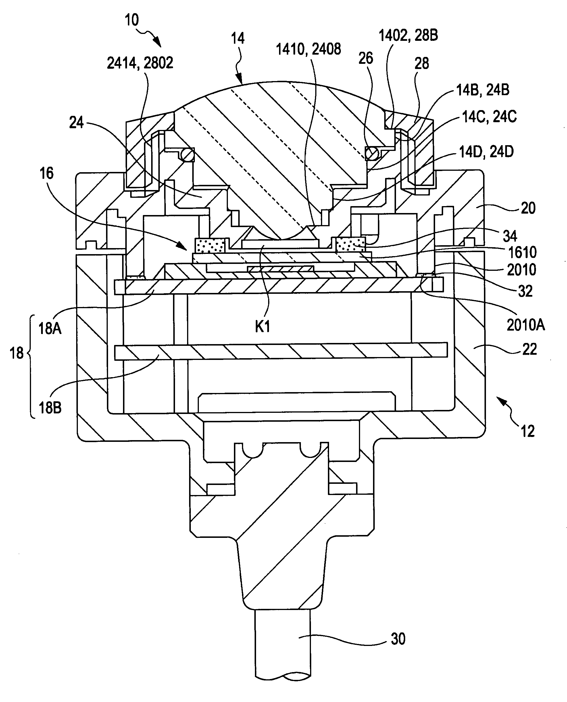
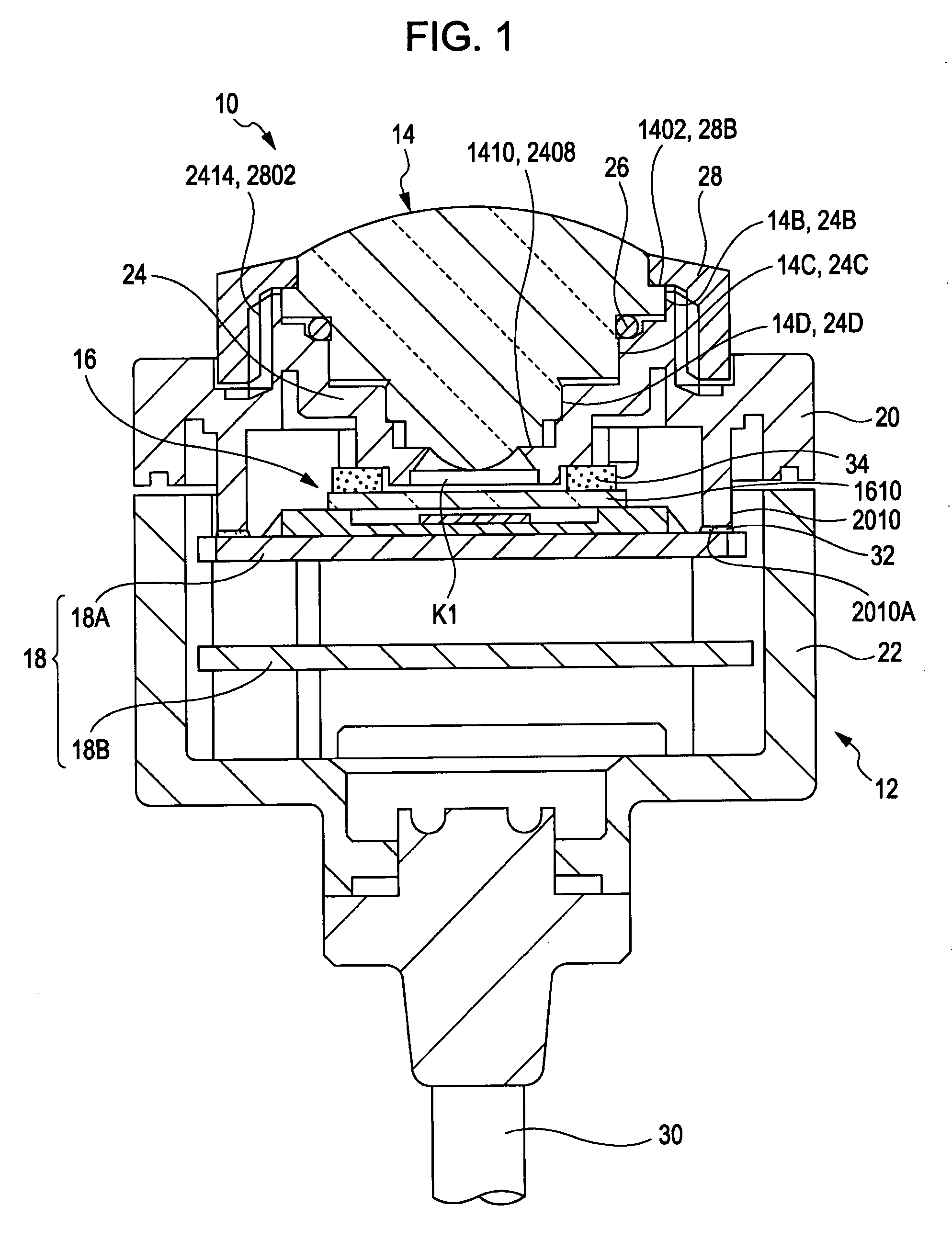
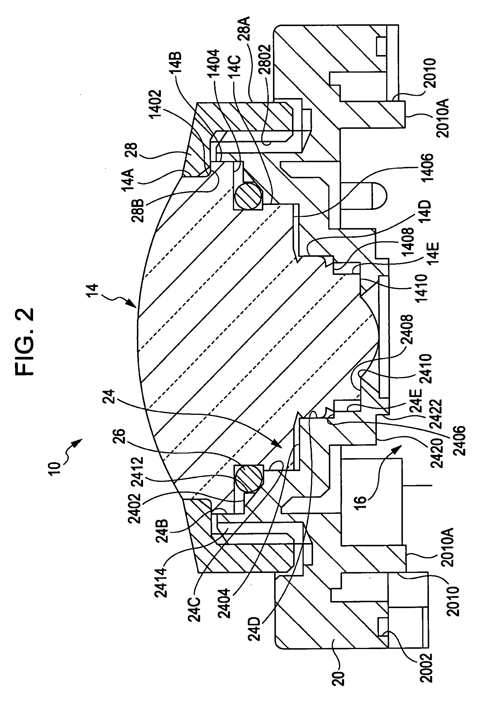
[0029]FIG. 1 is a cross-sectional view showing the overall configuration of an image pickup apparatus 10 according to an embodiment of the present invention. FIG. 2 is a cross-sectional view of the image pickup apparatus 10 before an image pickup device 16 and a printed wiring board 18 are mounted. FIG. 3 is a cross-sectional view of the image pickup apparatus 10 after the image pickup device 16 and the printed wiring board 18 are mounted.

[0030]The image pickup apparatus 10 shown in FIG. 1 is used, for example, as a car-mounted camera mounted outside a car body or inside a car cabin, or as an outside surveillance camera.

[0031]As shown in FIG. 1, the image pickup apparatus 10 includes a housing 12, a lens 14, an image pickup device 16, and a printed wiring board 18.

[0032]In this specification, a side close to a subject in the optical axis direction of an image capturing optical system is...


PUM


Abstract

An image pickup apparatus includes a housing, a lens incorporated in the front of the housing and configured to constitute an imaging optical system, an image pickup device provided in the housing and configured to capture a subject image guided by the imaging optical system, a printed wiring board provided in the housing and having the image pickup device mounted thereon, a barrel provided integrally with the front of the housing, an annular lens cover configured to push a face of the lens facing forward in a rearward direction, and detachably mounted on the front of the barrel, and a support wall projecting rearward outside a rear end of the barrel in the radial direction and inside the housing, and bonded to the printed wiring board with adhesive.

Description

CROSS REFERENCES TO RELATED APPLICATIONS[0001]The present invention contains subject matter related to Japanese Patent Application JP 2006-206344 filed in the Japanese Patent Office on Jul. 28, 2006 and Japanese Patent Application JP 2006-206408 filed in the Japanese Patent Office on Jul. 28, 2006, the entire contents of which are incorporated herein by reference.BACKGROUND OF THE INVENTION[0002]1. Field of the Invention[0003]The present invention relates to an image pickup apparatus.[0004]2. Description of the Related Art[0005]Image pickup apparatuses having an image pickup device, such as a CCD image sensor or a CMOS image sensor, have been proposed.[0006]These image pickup apparatuses are used as digital still cameras or video cameras, car-mounted cameras mounted outside a car body or inside a cabin, as outside surveillance cameras.[0007]Most image pickup apparatuses used as car-mounted cameras or surveillance cameras include a housing serving as an outer casing, a barrel incorpo...

Claims


Application Information

Patent Timeline
Patent Type & Authority Applications(United States)
IPC IPC(8): G02B7/02
CPCG02B7/022H04N5/2254H04N5/2253H04N5/2252H04N23/51H04N23/55H04N23/54
Inventor IWASAKI, KEIICHI
Owner SONY CORP
Learn More