
Method Of and System For Setting Laser Processing Conditions, Laser Processing System, Computer Program For Setting Laser Processing Conditions, Computer Readable Medium and Recording Device On Which Laser Processing Conditions Are Recorded

a laser processing and laser processing technology, applied in the field of laser processing system, can solve the problems of hard users experienced only in creating two-dimensional laser processing data to create three-dimensional processing data, and achieve the effect of convenient confirmatory operation, convenient recognition, and convenient operation

Active Publication Date: 2008-01-31
KEYENCE
View PDF38 Cites 50 Cited by
  • Summary
  • Abstract
  • Description
  • Claims
  • Application Information

AI Technical Summary

Benefits of technology

[0018] The laser processing data setting system allows users to edit three-dimensional laser processing data in two dimensions. As a consequence, the laser processing data setting system enables even users who are unfamiliar with three-dimensional data editing to achieve complicated of processing data setting with a three dimensional representation. Since the display means can be changed between a two dimensional display mode and a three dimensional display mode, or otherwise, can coincidentally display a two dimensional representation and a three dimensional representation of the processing data as appropriate, it is facilitated to perform confirmatory operation according to data setting operation.
[0019] Furthermore, a two dimensional representation of the processing data is displayed in plane, namely an X-Y plane, Y-Z plane and Z-X plane, as viewed from a view point or a laser irradiation source, it can be recognized how a processing pattern deforms or distorts. For example, in the case where a barcode is printed on a cylindrical or columnar work surface, it is easily recognized how narrow spaces distort. A three dimensional representation of the processing data can be quickly changed to a display in a desired plane. This facilitates confirmatory operation of a view point. The exclusive edit mode which excludes users from three dimensional data editing and is enabled by default upon activation of the laser processing data setting system is convenient for users who are unfamiliar with three-dimensional data editing.
[0020] Detection of a warning about a defective work surface area of a work and surface facilitates confirmatory operation as to whether a processing pattern falls within a processable work surface area as desired. The confirmatory operation which is made even during processing data setting saves users the trouble of setting processing data and enables users to efficiently achieve processing data setting, so that a user-friendly environment for processing data setting is realized.

Problems solved by technology

However, because the three dimensional processing data requires a greater number of parameters regarding print locations as compared with two dimensional processing data, it is hard for users experienced only in creating two-dimensional laser processing data to create three dimensional processing data by use of the laser processing data setting program just as they intended.

Method used


Image

  • Method Of and System For Setting Laser Processing Conditions, Laser Processing System, Computer Program For Setting Laser Processing Conditions, Computer Readable Medium and Recording Device On Which Laser Processing Conditions Are Recorded
  • Method Of and System For Setting Laser Processing Conditions, Laser Processing System, Computer Program For Setting Laser Processing Conditions, Computer Readable Medium and Recording Device On Which Laser Processing Conditions Are Recorded
  • Method Of and System For Setting Laser Processing Conditions, Laser Processing System, Computer Program For Setting Laser Processing Conditions, Computer Readable Medium and Recording Device On Which Laser Processing Conditions Are Recorded

Examples


Embodiment Construction

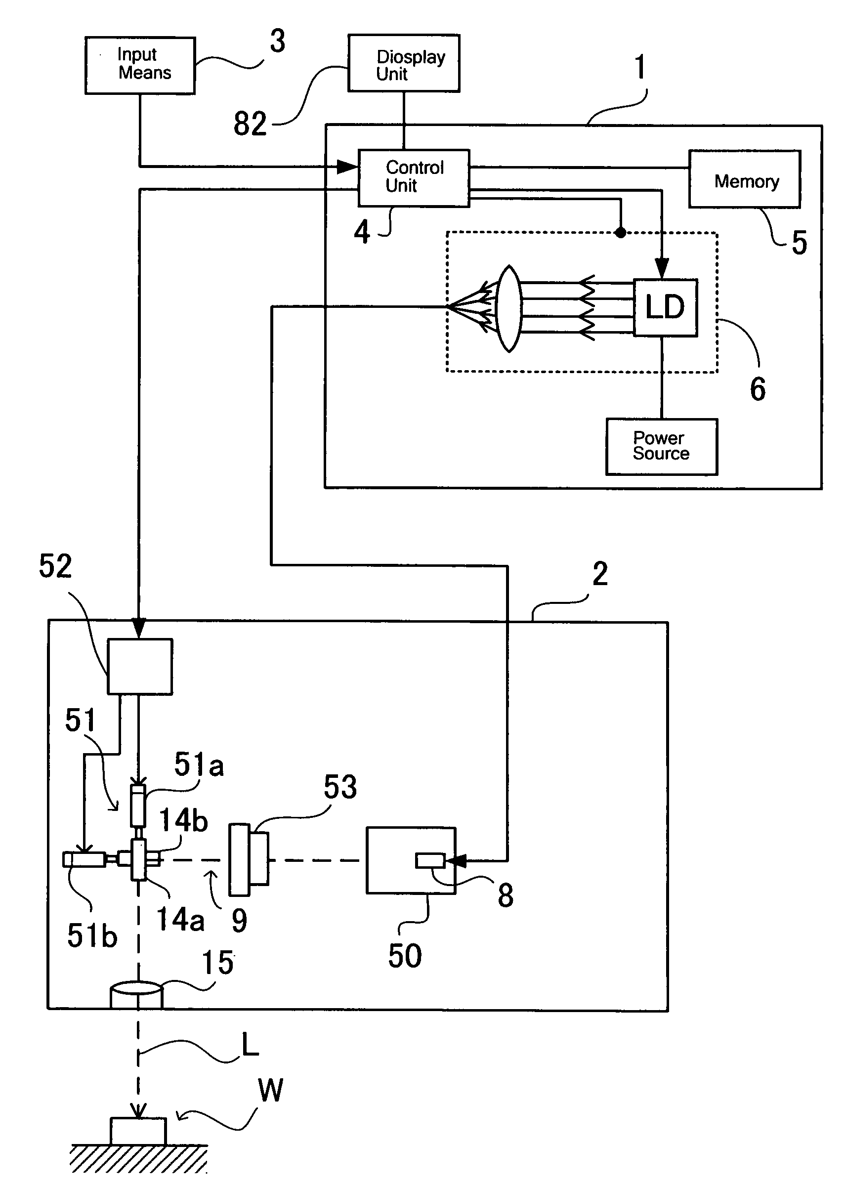
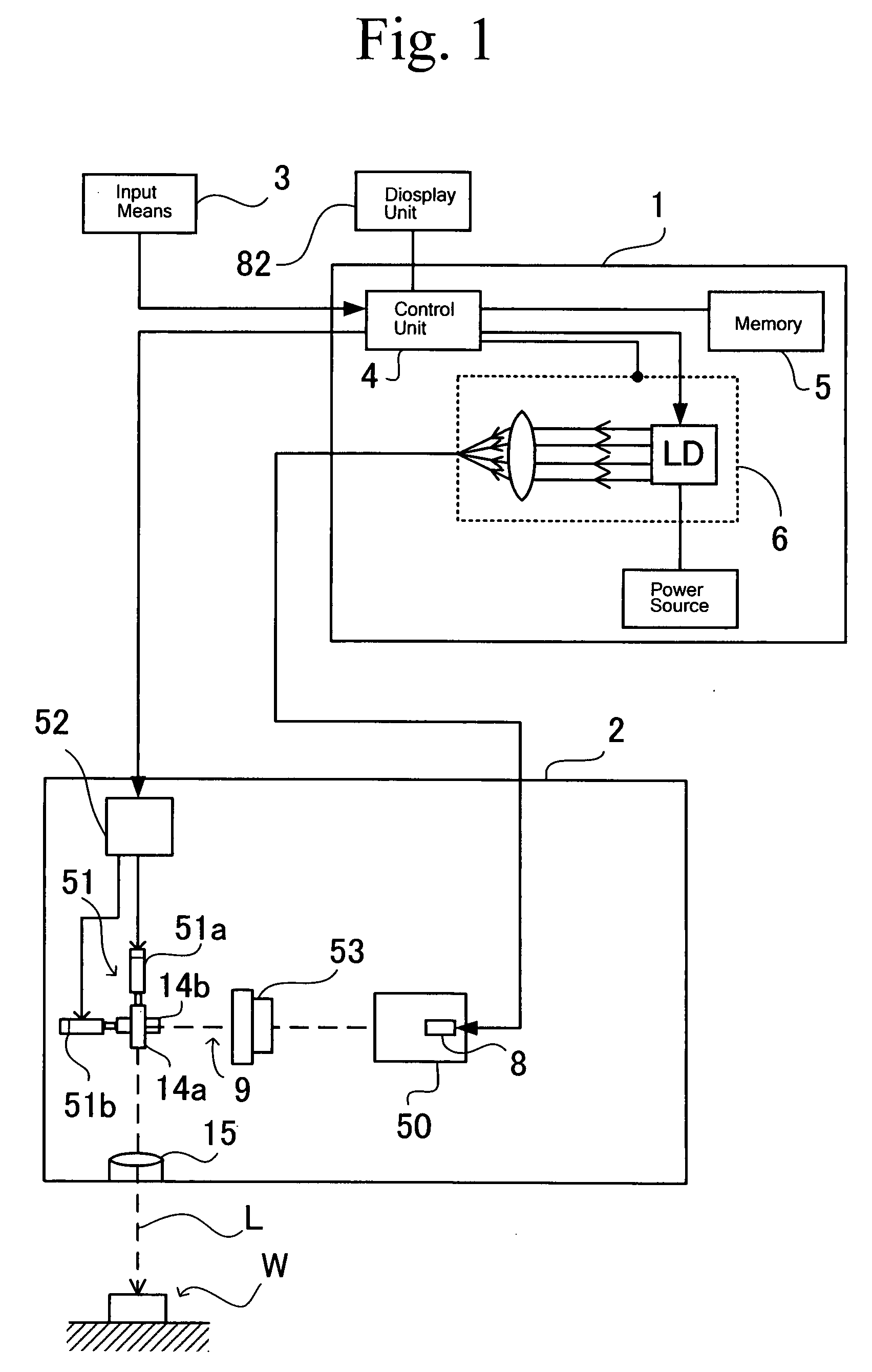
[0124] Hereinafter, embodiments will be concretely described with reference to the accompanying drawings. Although the following description is directed to a method of and a system for setting processing conditions of a laser processing system such as a laser marker which performs processing such as printing or marking including characters, symbols and graphics on work with a laser beam, a computer program for setting processing conditions for a laser processing system, a computer-readable recording medium or device on which laser processing conditions are recorded, nevertheless, the it should be appreciated that the present invention has broader applications and is not limited to this particular embodiments.

[0125] Further, in the following description, various changes and modifications may be made in form, size, relative arrangement of constituent components and means of the described system and apparatus unless otherwise specified distinctively. It is intended that all matter con...


PUM

PropertyMeasurementUnit
central wavelengthaaaaaaaaaa
wavelengthaaaaaaaaaa
diameteraaaaaaaaaa

Abstract

A method of setting processing data for a computer-assisted laser processing apparatus is disclosed, along with a system for setting a laser processing data. The method comprises a function of setting a three-dimensional profile of a object and a processing pattern as processing conditions, a function of generating processing data representing the processing conditions for the object, and a function of visually displaying a two dimensional representation of the processing data on a display screen and a function of setting a three-dimensional profile of a object and a processing pattern as processing conditions, wherein it is enabled to set the three-dimensional profile and the processing pattern while displaying the object in two dimensions on the display screen disposed within a processing zone.

Description

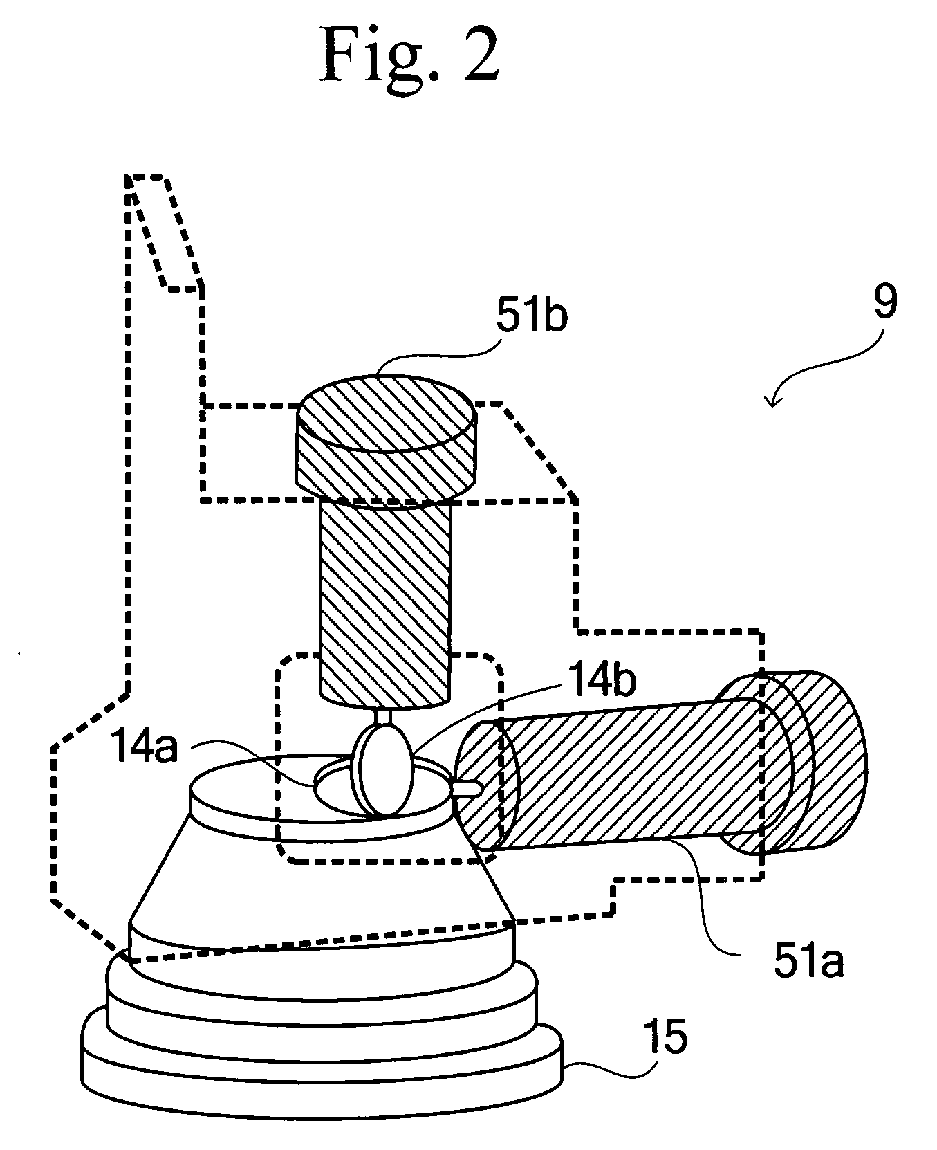
BACKGROUND OF THE INVENTION [0001] 1. Field of the Invention [0002] The present invention relates to a method of and a system for setting processing conditions of a laser processing system such as a laser marker which performs processing such as printing or marking including characters, symbols and graphics on work with a laser beam, a computer program for setting processing conditions for a laser processing system, a computer-readable recording medium or device on which laser processing conditions are recorded. [0003] 2. Description of Related Art [0004] A laser processing system scans a given scan field of a subject surface of works (work surfaces) such as components and finished products with a laser beam to apply processing, such as printing and marking of characters, symbols and / or graphics, to the work surfaces. Referring to FIGS. 1 and 2 for the purpose of providing a brief description of a configuration of a laser processing system by way of example, the laser processing sys...

Claims


Application Information

Patent Timeline
Patent Type & Authority Applications(United States)
IPC IPC(8): B23K26/067G06F19/00B23K26/00B23Q15/00G05B19/409
CPCB23K26/0807B23K26/082B23K26/03
Inventor IDAKA, MAMORUYAMAKAWA, HIDEKI
Owner KEYENCE
Learn More