
Arrangement of Light-Emitting Diodes Of LED Lamp

Inactive Publication Date: 2008-01-24
AUGUX CO LTD
View PDF6 Cites 19 Cited by
  • Summary
  • Abstract
  • Description
  • Claims
  • Application Information

AI Technical Summary

Benefits of technology

[0007]The present invention is to provide an improved arrangement of light-emitting diodes of a LED lamp, which cooperates with the circular illuminating surface of the common lamp to allow each light-emitting diode to be arranged in a circular form. In this way, it is not only helpful to design the second-ordered optical lens of the LED lamp, but also to produce a conductive circuit by means of series connection, parallel connection or the combination of the two. Thus, the conductive circuit will not be affected by the arrangement of each light-emitting diode to cause the difficulty in layout and design.

Problems solved by technology

Thus, the conductive circuit will not be affected by the arrangement of each light-emitting diode to cause the difficulty in layout and design.

Method used


Image

  • Arrangement of Light-Emitting Diodes Of LED Lamp
  • Arrangement of Light-Emitting Diodes Of LED Lamp
  • Arrangement of Light-Emitting Diodes Of LED Lamp

Examples


first embodiment

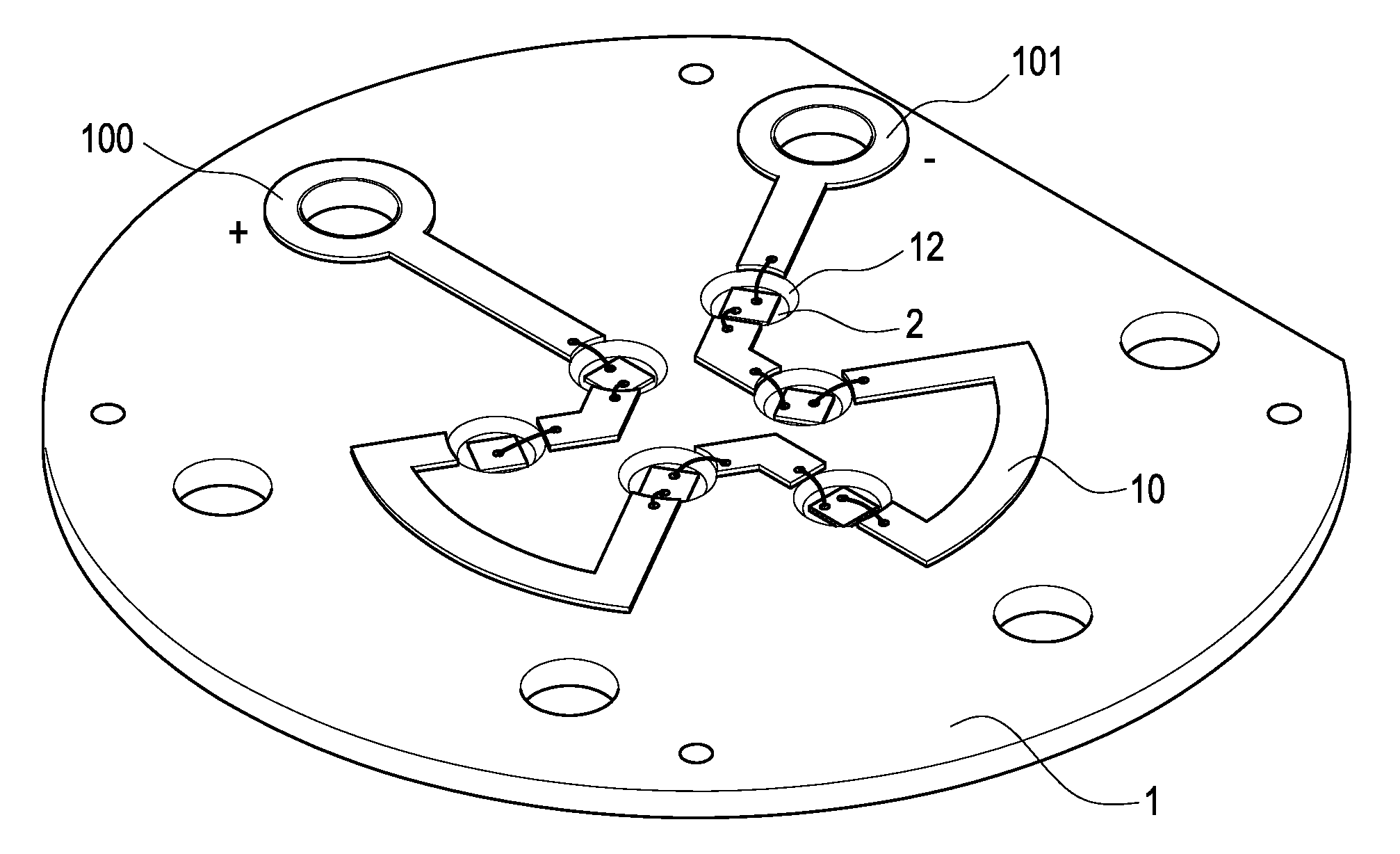
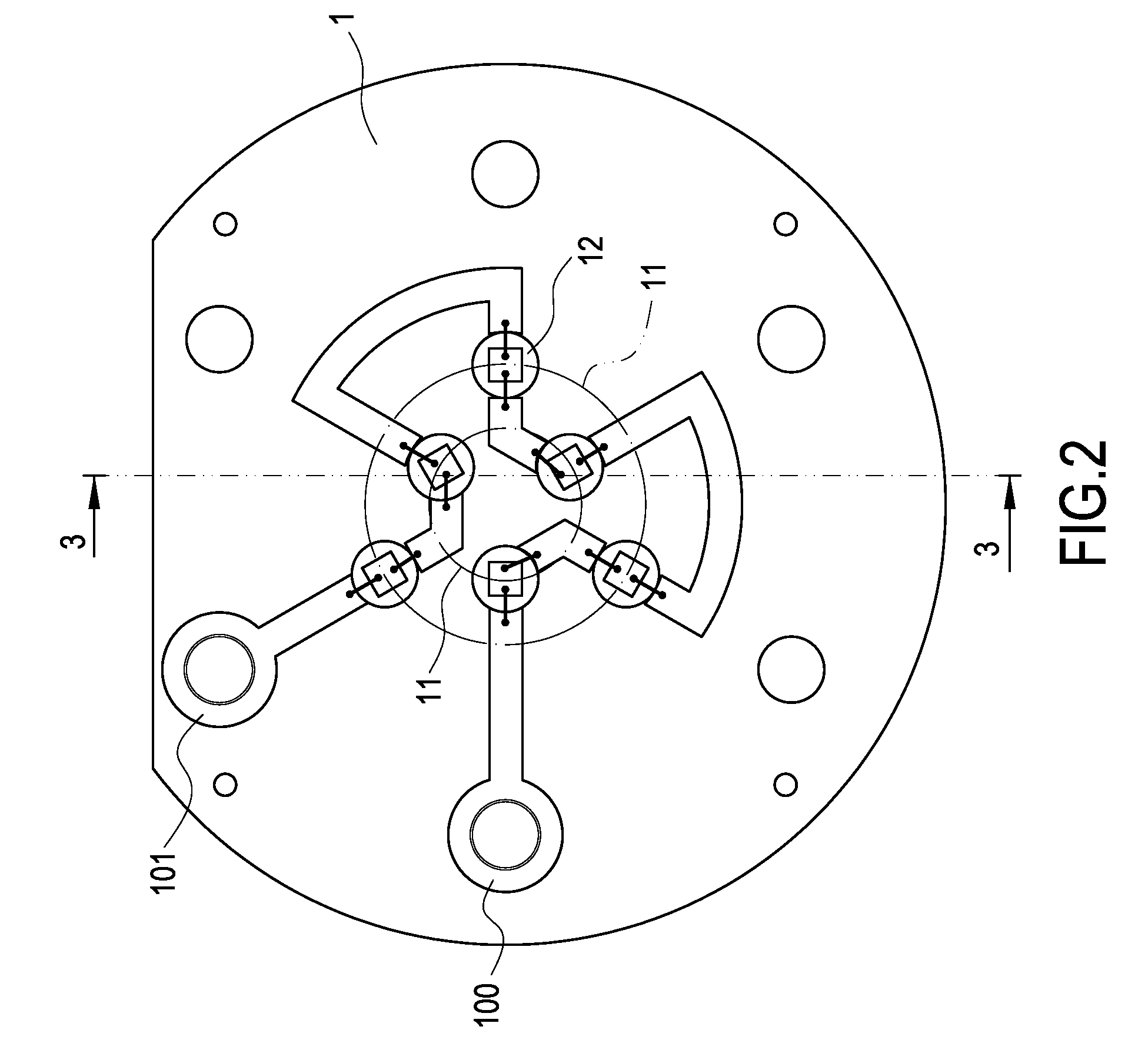
[0016]With reference to FIG. 1 and FIG. 2, which are a perspective view and a top plane view of the present invention, respectively. The present invention provides an improved arrangement of light-emitting diodes of a LED lamp, which comprises a circuit board 1 and a plurality of light-emitting diodes (LED) 2 provided on the circuit board 1.

[0017]The circuit board 1 is an insulating plate. A layer of conductive circuit 10 formed of metallic conductive materials such as copper foil is plated on the surface of the circuit board, so that each light-emitting diode 2 arranged thereon can be electrically connected in series connection or parallel connection. The external appearance and the size of the circuit board 1 can be designed according to the lamps to be used. Further, the number of the light-emitting diodes 2 can be determined according to the conditions in practice.

[0018]The characteristic of the present invention lies in that the arrangement of the light-emitting diodes 2 on the...

second embodiment

[0021]In addition, as shown in FIG. 4, in the present invention, every three adjacent light-emitting diodes 2 are electrically connected in series on the conductive circuit 10, and the thus-connected light-emitting diodes 2 are electrically connected in parallel connection. Since the light-emitting diodes are arranged in a circular shape and the light-emitting diodes 2 in the inner and outer imaginary circles 11 are staggered, each light-emitting diode 2 has a sufficient space for the design and layout of the conductive circuit 10. In other words, in the present invention, the circular arrangement of each light-emitting diode 2 helps to produce the conductive circuit 10 in series connection, parallel connection or the combination of the two. Also, the conductive circuit 10 will not be affected by the arrangement of each light-emitting diode to cause the difficulty in layout and design.

[0022]Further, as shown in FIG. 5 and FIG. 6, at the position in which each light-emitting diode 2 ...


PUM


Abstract

An improved arrangement of light-emitting diodes of a LED lamp includes a circuit board and a plurality of light-emitting diodes. The surface of the circuit board is provided with a layer of conductive circuit, so that the light-emitting diodes can be arranged on the circuit board and electrically connected to the conductive circuit. On the surface of the circuit board provided with the conductive circuit, an imaginary circle is defined. Further, the light-emitting diodes are distributed on the circuit board along the imaginary circle to form a circular arrangement.

Description

BACKGROUND OF THE INVENTION[0001]1. Field of the Invention[0002]The present invention relates to an improved arrangement of light-emitting diodes of a LED lamp, and in particular to an improved arrangement of light-emitting diodes of a LED lamp, in which the light-emitting diodes are arranged in a circular form.[0003]2. Description of Prior Art[0004]Since light-emitting diodes (LED) are high-intensity, energy-saved and long-life, they are widely used in the illumination of electronic devices or lamps. Further, in order to increase the illuminating range and intensity thereof, a plurality of light-emitting diodes are usually combined to form a LED lamp set, thereby to form an illuminating surface by those light-emitting diodes.[0005]The illuminating surface of a common lamp is usually formed into a circular shape. However, the light-emitting diodes provided on the LED lamp set are currently arranged on its circuit board in an array, which is not suitable for the design of the second-...

Claims


Application Information

Patent Timeline
IPC IPC(8): F21V21/00
CPCF21K9/00F21Y2103/33H01L2224/48091H01L2224/8592H01L2924/00014
Inventor WANG, PEI-CHOA
Owner AUGUX CO LTD
Learn More