
Single-phase position sensorless permanent magnet motor control apparatus

a permanent magnet motor and sensorless technology, applied in the direction of motor/generator/converter stopper, electronic commutator, dynamo-electric converter control, etc., can solve the problems of large noise and vibration of motors, insufficient handling of vibration and noise, etc., to achieve low noise, low cost, and low vibration

Inactive Publication Date: 2008-01-24
JAPAN SERVO CO LTD
View PDF5 Cites 14 Cited by
  • Summary
  • Abstract
  • Description
  • Claims
  • Application Information

AI Technical Summary

Benefits of technology

[0015]Therefore, an object of the present invention is to provide a low noise, low vibration single-phase permanent magnet motor control apparatus that eliminates the problems of the conventional art described heretofore and that is little in efficiency falling and a fan or pump using the single-phase permanent magnet motor control apparatus.
[0016]The example described in JP-A-2004-88870 brings about an effect that the torque ripple is reduced to some extent with a simple configuration.
[0018]Therefore, another object of the present invention is to solve the problems of the conventional art described heretofore, cope with load variation to some extent, reduce the torque ripple, and thereby provide a low vibration, low noise, low cost single-phase permanent magnet motor control apparatus and a fan and a pump using the single-phase permanent magnet motor control apparatus.
[0020]As a result, it is possible to provide a low torque ripple, low noise, low vibration, high efficiency single-phase position sensorless permanent magnet motor.
[0022]As a result, it is possible to provide a low vibration, low noise, low cost single-phase permanent magnet motor control apparatus, and a fan and a pump using the single-phase permanent magnet motor control apparatus.

Problems solved by technology

Therefore, there is a fear that efficiency drop and an increase in pulsating torque might be caused, resulting in a motor yielding large noise and vibration.
When the number of revolutions has changed, when the load has changed, or when the temperature has changed, however, it cannot be coped with sufficiently and there is a fear that torque ripple might be generated resulting in vibration and noise.

Method used


Image

  • Single-phase position sensorless permanent magnet motor control apparatus
  • Single-phase position sensorless permanent magnet motor control apparatus
  • Single-phase position sensorless permanent magnet motor control apparatus

Examples


Embodiment Construction

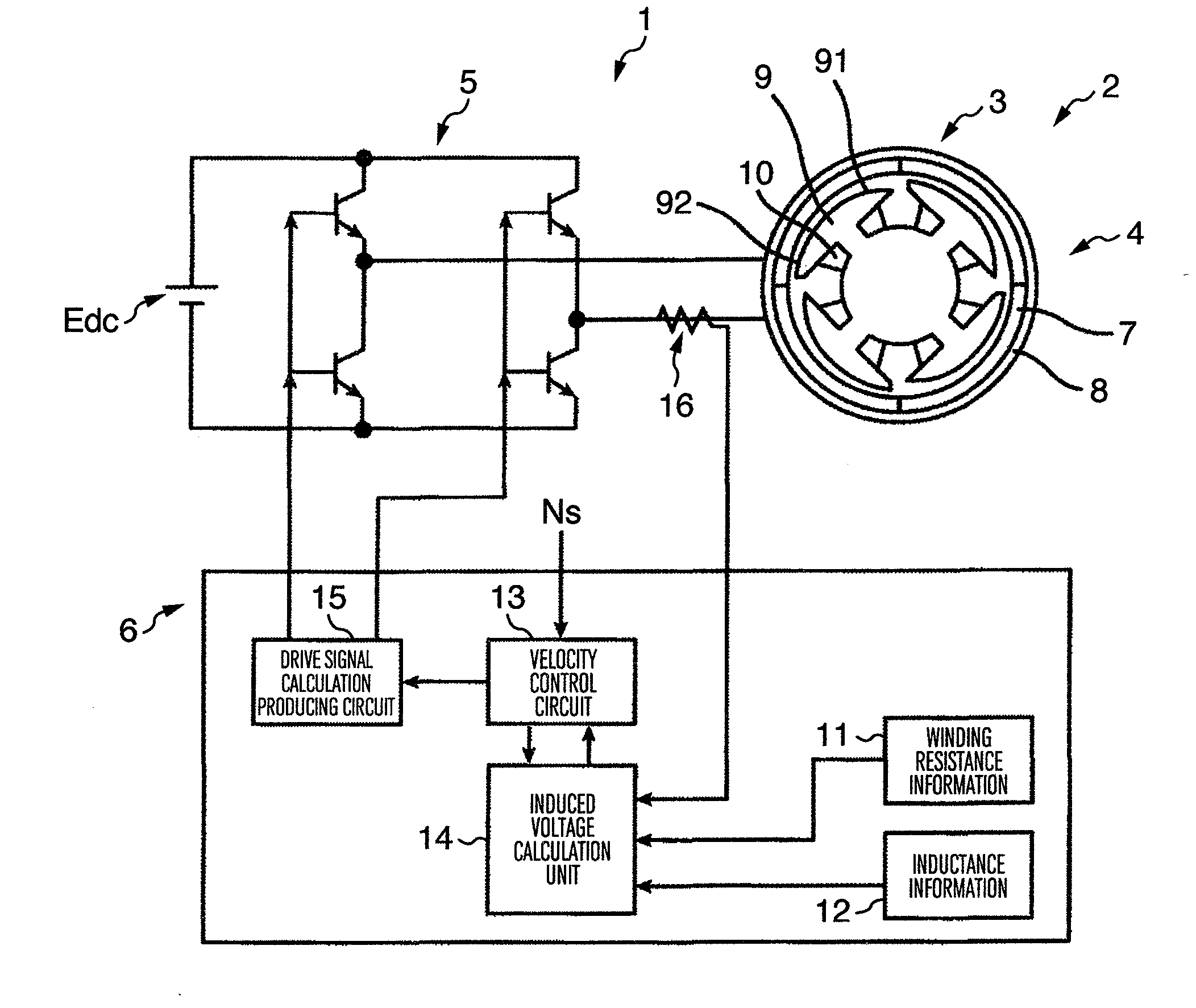
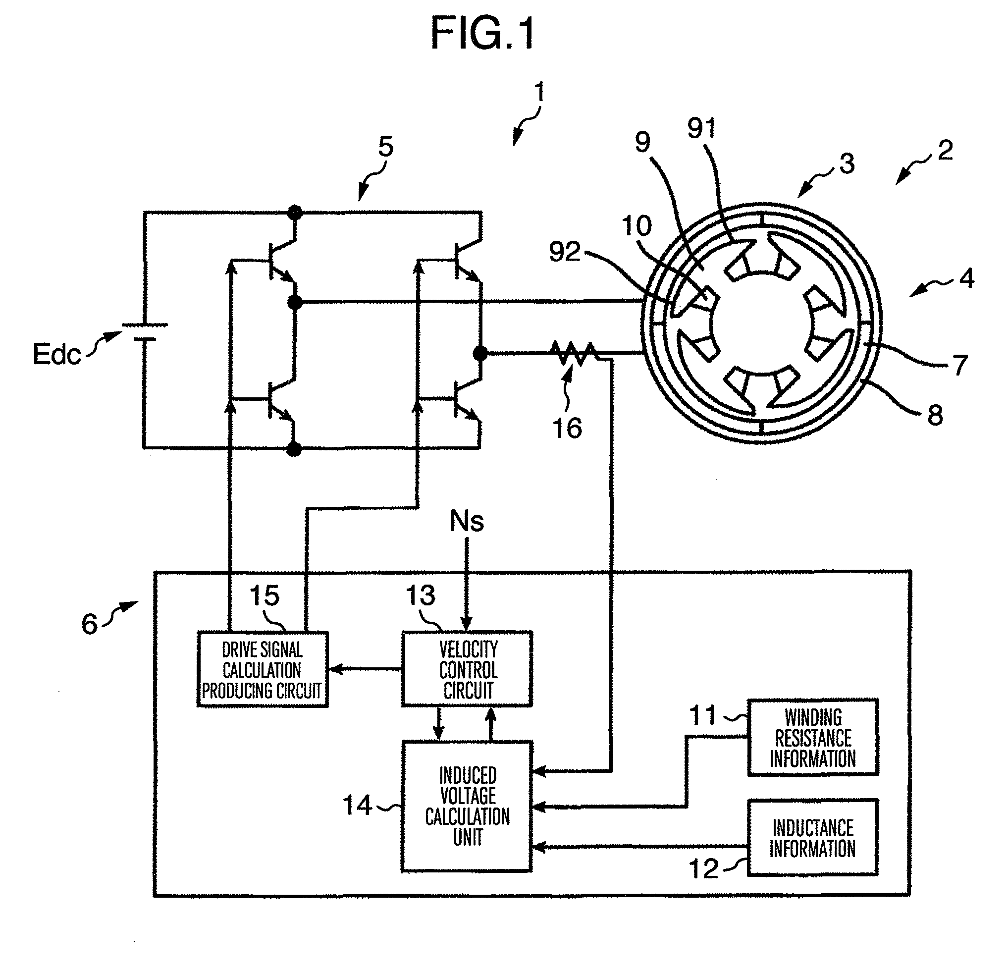
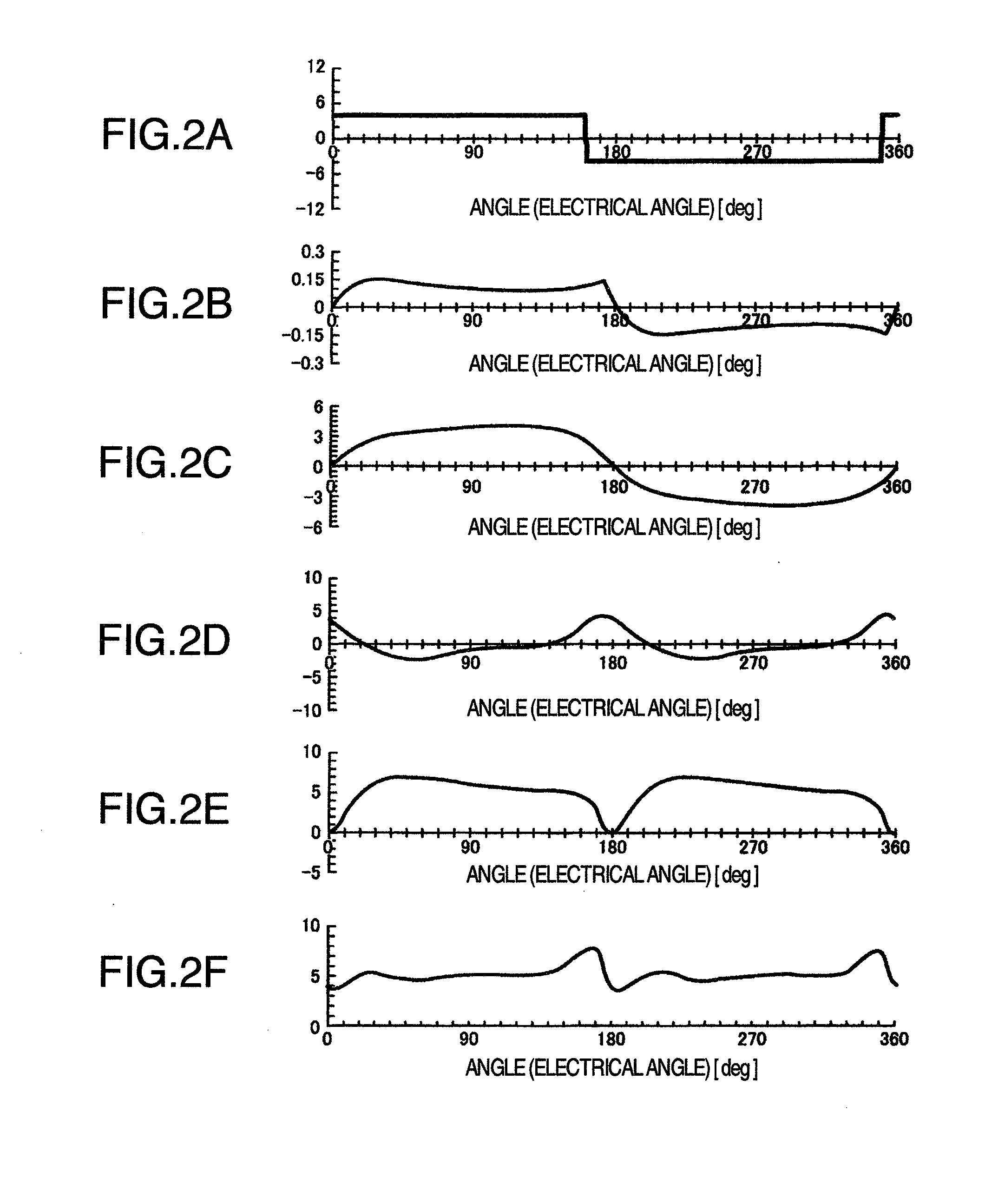
[0032]FIG. 1 shows a configuration of a single-phase position sensorless permanent magnet motor control apparatus according to an embodiment of the present invention. FIGS. 2A to 2F show its operation explanation diagrams.

[0033]In FIG. 1, a single-phase position sensorless permanent magnet motor control apparatus 1 includes a single-phase permanent magnet motor 2, a conversion circuit 5 which functions to supply AC power from a DC power supply Edc to the single-phase permanent magnet motor 2, and a control circuit 6 which controls an output current of the conversion circuit 5.

[0034]The single-phase permanent magnet motor 2 includes a stator 3 and a rotor 4. In the ensuing description, it is supposed that the motor is the so-called outer rotor type motor in which the stator 3 is disposed on an inner circumference and the rotor 4 is disposed on an outer circumference. However, similar description holds true of the inner rotor type motor or other motors. In the shown example, the numbe...


PUM


Abstract

A single-phase permanent magnet motor control apparatus, in particular, a low price, flat output torque, low vibration, low noise single-phase permanent magnet motor control apparatus, and a fan and pump using such a single-phase permanent magnet motor control apparatus are provided. In a single-phase permanent magnet motor control apparatus for driving a single-phase permanent magnet motor by using a DC power supply, a converter for converting DC to AC, and a control circuit for controlling the converter, a motor current measuring unit, a terminal voltage measuring unit, a correction unit for correcting an impedance drop in motor constants, and a calculation unit for finding an induced voltage to be obtained by control are included, and a polarity of a terminal voltage is determined on the basis of a value of the found induced voltage.

Description

BACKGROUND OF THE INVENTION[0001]The present invention relates to a single-phase position sensorless permanent magnet motor control apparatus. In particular, the present invention provides a low vibration, low noise, small-sized, light weight, low-cost single-phase position sensorless permanent magnet motor control apparatus which runs and controls a single-phase permanent magnet motor and consequently which is suitable to mount on a vehicle such as an automobile.[0002]The present invention relates to a single-phase permanent magnet motor control apparatus. In particular, the present invention relates to a low price, flat output torque, low vibration, low noise single-phase permanent magnet motor control apparatus, and a fan and a pump using such a single-phase permanent magnet motor control apparatus.[0003]A single-phase permanent magnet motor control apparatus is used as a fan drive source.[0004]As compared with an ordinary three-phase motor, the single-phase permanent magnet moto...

Claims


Application Information

Patent Timeline
IPC IPC(8): H02P6/18
CPCH02P23/14H02P6/18
Inventor TAJIMA, FUMIOKAKUGAWA, SHIGERUKITAMURA, MASASHIKAWAMATA, SHOICHIKANAZAWA, HIROSHIKOYAMA, TAKAYUKIOHIWA, SHOJISEKIGUCHI, OSAMU
Owner JAPAN SERVO CO LTD
Learn More