
Photovoltaic receiver for beamed power

a technology of photovoltaic and power system, applied in the direction of pv power plants, light radiation electric generators, generators/motors, etc., can solve the problems of limited flight range and flight duration of aircraft, limited speed and cargo capacity, and reduced resistance losses of aircraft, so as to reduce resistive losses and uniform irradiance of laser beams , the effect of increasing the average power level

Active Publication Date: 2008-01-24
THE BOEING CO
View PDF14 Cites 12 Cited by
  • Summary
  • Abstract
  • Description
  • Claims
  • Application Information

AI Technical Summary

Benefits of technology

The present invention is about using laser beams to power a photovoltaic (PV) array on an airborne vehicle. The surface geometry of the PV array is designed to ensure even distribution of laser beam power across the array, resulting in higher average power levels and more uniform irradiation. This technology also reduces resistive losses and allows for unlimited flight duration for surveillance, weather monitoring, and communications relays. Overall, this invention provides a more efficient and reliable way to convert laser beam power to electrical energy.

Problems solved by technology

Currently, aircraft are limited in flight range and flight duration because of fuel capacity and fuel consumption.
These limits require aircraft to return for refueling and also prevent them from unlimited flight ranges.
Further, aircraft are also limited by weight constraints, such as the weight of the fuel necessary for travel that limits the speed and cargo capacity of the aircraft.
Some airplanes use solar power to eliminate these issues, however solar power systems experience power reductions due to weather and atmospheric changes, the Earth's annual and diurnal cycles, or solar eclipses.
Current systems that provide laser-beamed power to aircraft by using photovoltaic (PV) arrays and receivers have problems with obtaining uniformity of power transfer across the PV array.
However, the planar PV array does not experience a uniform irradiance across all the cells in the array when illuminated with laser-beamed power.
The irradiance received by a planar laser-power PV receiver is therefore non-uniform, with the strongest rays at the center of the PV array and weaker rays impinging upon the PV cells toward the edges of the PV array.
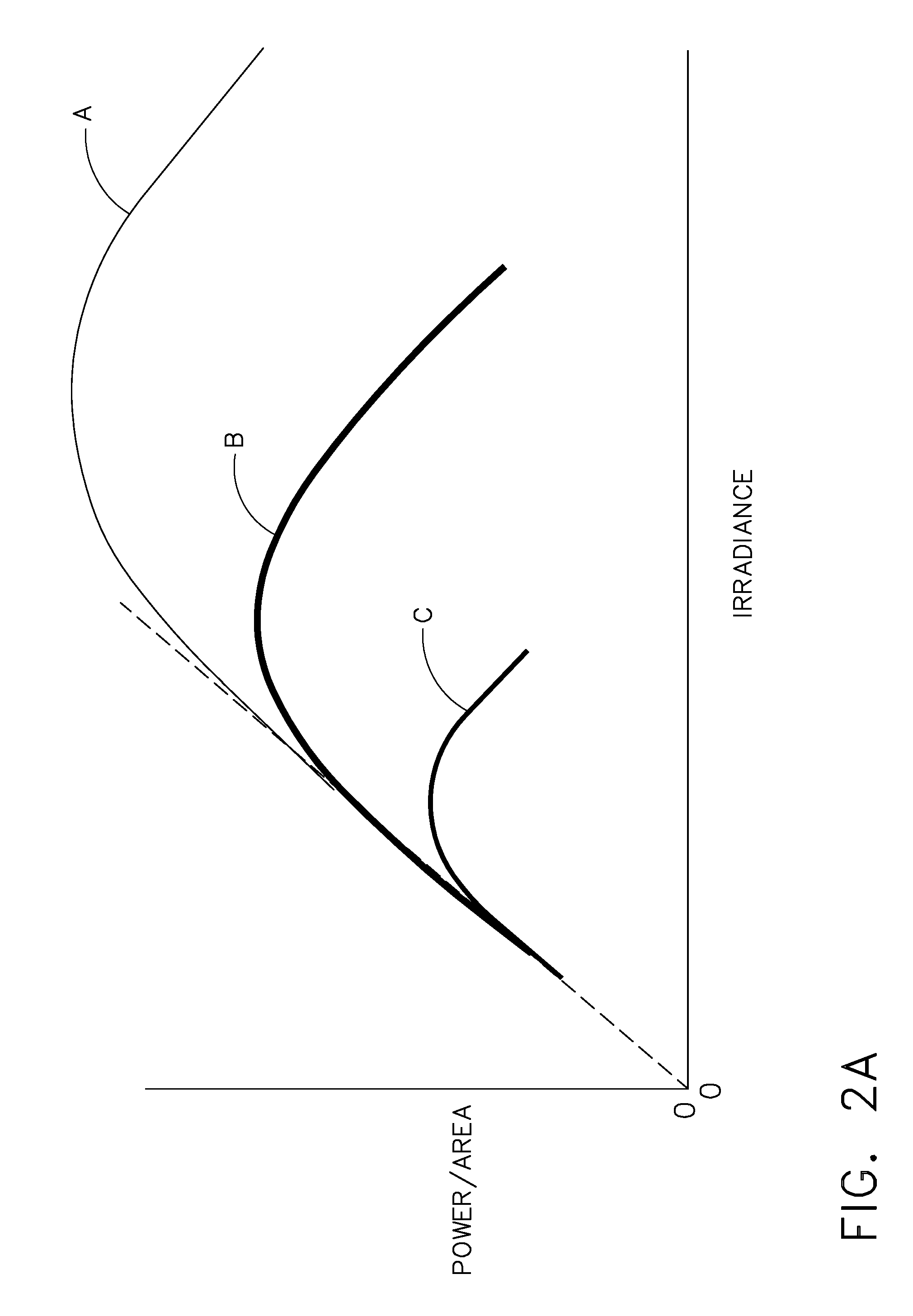
If a PV array is designed for optimum efficiency at the lower irradiance levels at the edges, the PV array will likely experience overheating at the center of the array, because the PV cells in the center are not rated for the higher irradiance beams incident on the center.
The overheating of the PV cells at the center increases their electrical resistance and therefore increases resistive losses for the array.
Conversely, a PV array designed for optimum efficiency at the high irradiance in the center of the PV array results in reduced average power production per PV cell, i.e. the PV cells at the edge do not receive the total irradiance for which they are rated, resulting in reduced power output.
In either case, costly resources, i.e. PV cells, are used below their optimum capacity.
Another deficiency in current planar PV arrays systems is that atmospheric inhomogeneities create rapid variations in refractivity across the width of the laser beam.
Greater current from one cell increases the I2 R losses of all cells in the string and results in greater overall average losses for the entire array.
Thus, in view of the disadvantages of the current methods and systems, and in view of the current demand in the relevant art, what is needed is a method and system to provide PV laser-beamed power to satellites and aircraft while mitigating the effects of the current unsteady, non-uniform illumination in these systems.

Method used


Image

  • Photovoltaic receiver for beamed power
  • Photovoltaic receiver for beamed power
  • Photovoltaic receiver for beamed power

Examples


Embodiment Construction

[0033]The present invention is directed to a method and system for using photovoltaic (PV) arrays to provide optical beamed power to satellites, aircraft, and other similar apparatus. The optical beamed power can include, but is not limited to laser beams, infrared beams, and ultraviolet rays. When used herein, the term “laser” is understood to include any form of optical beam, and the terms are used interchangeably herein. The present invention employs laser-power beams incident on a PV array to provide steady, uniform illumination, while reducing or eliminating the diurnal, seasonal, and geographic variations that are inherent with solar power.

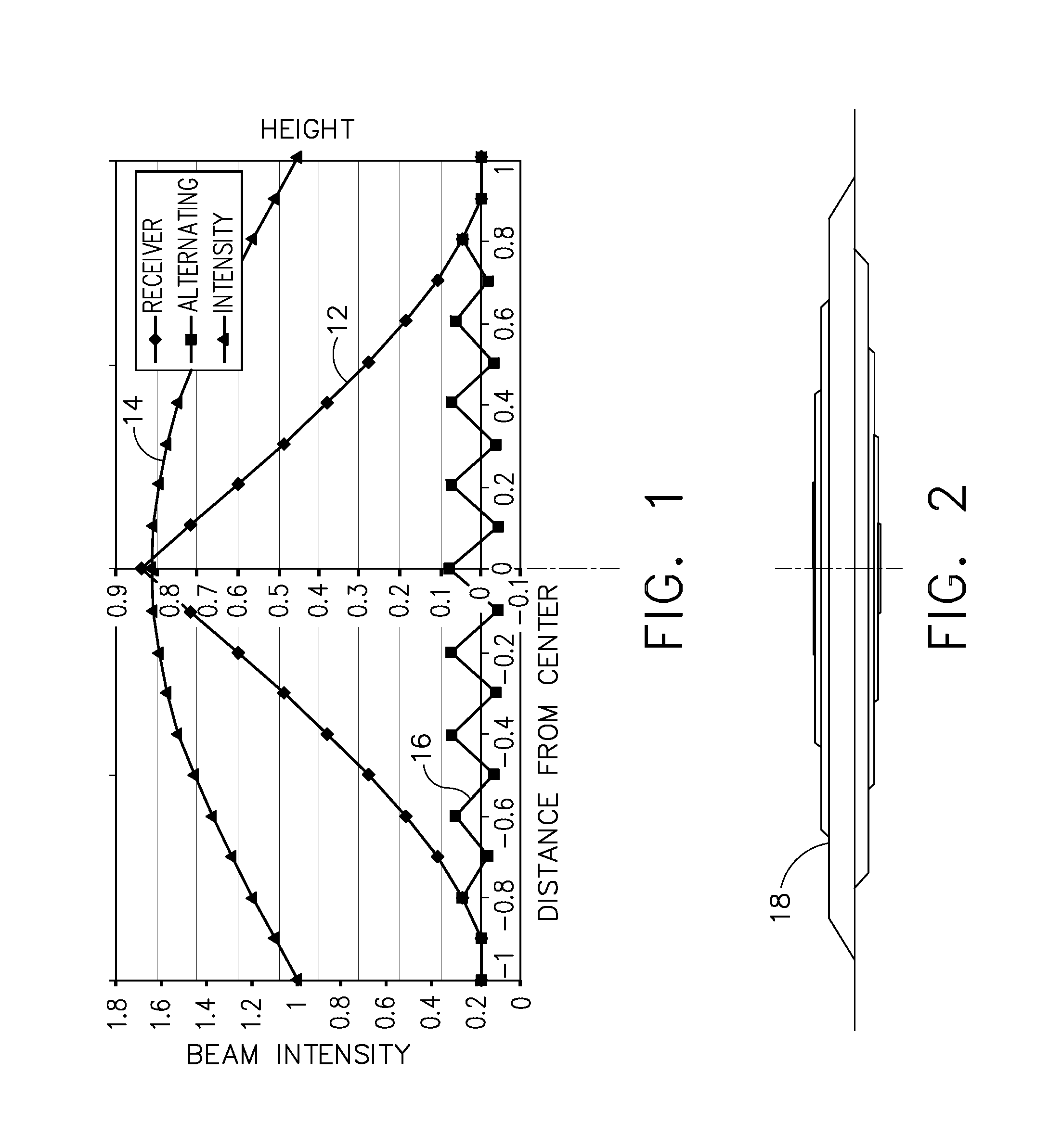
[0034]Referring first to FIG. 1, a graph shows alternate configurations for a PV array 12, 16 and a curve 14 showing the beam intensity that is approximately identical for both PV array configurations 12, 16. First there is shown a curved, approximately conical profile 12 of a PV array with a cusp and slopes, and a curve 14 of the beam inten...


PUM


Abstract

A system and method directed to using a PV array and laser beamed-power for aircraft and satellites is provided. More specifically, a system and method directed to a PV receiver that reduces power losses caused by variations in irradiance is provided. The use of a sloped array with a grooved cover glass coated with reflective coating allows the system and method to receive the laser beamed power at an angle and reduce any losses while producing a maximum power output. In addition, the use of capacitors in parallel with the PV cells in the array reduces resistive losses caused by short-term optical fluctuations and assists in maximizing power output for the array.

Description

FIELD OF THE INVENTION[0001]The present invention is directed to photovoltaic (PV) receivers for beamed power system. More specifically, the present invention is directed to an improved PV receiver that reduces inefficiency caused by overheating of PV cells and reduces resistive losses caused by fluctuations in irradiance.BACKGROUND OF THE INVENTION[0002]Currently, aircraft are limited in flight range and flight duration because of fuel capacity and fuel consumption. These limits require aircraft to return for refueling and also prevent them from unlimited flight ranges. Further, aircraft are also limited by weight constraints, such as the weight of the fuel necessary for travel that limits the speed and cargo capacity of the aircraft. Some airplanes use solar power to eliminate these issues, however solar power systems experience power reductions due to weather and atmospheric changes, the Earth's annual and diurnal cycles, or solar eclipses. Therefore, aircraft that use solar powe...

Claims


Application Information

Patent Timeline
Patent Type & Authority Applications(United States)
IPC IPC(8): H02N6/00
CPCH01L31/0232H02J5/00H01L31/0547H01L31/0543Y02E10/52
Inventor TILLOTSON, BRIAN J.
Owner THE BOEING CO
Learn More