
Apparatus and Method for Scatter Correction in Projection Radiography

a projection radiography and apparatus technology, applied in the field of apparatus for projection radiography, can solve the problems of increasing noise, image quality impairment, and inability to use a grid, and achieve the effect of low computational complexity

Active Publication Date: 2008-01-17
SIEMENS HEATHCARE GMBH
View PDF7 Cites 33 Cited by
  • Summary
  • Abstract
  • Description
  • Claims
  • Application Information

AI Technical Summary

Benefits of technology

[0109] The solution proposed here has the following advantages:
[0110] If required, the method can be incorporated in existing mammography machines without mechanical reconstruction.
[0111] Moreover it is a method which on the one hand shares the adequacy of physical modeling using the Monte Carlo method, but on the other hand—because all the time-consuming calculations are carried out in advance where possible and the necessary data is stored in tables—ultimately involves relatively low computational complexity for the scatter correction.
[0112] The modeling accuracy of the scatter correction described here is essentially greater than that of the known (analytical) physical models, as a number of simplifying assumptions and approximations can be dispensed with.
[0113] The possibilities of the scatter correction proposed here go far beyond the possibilities of the long kn

Problems solved by technology

The scatter produced in the object under examination (breast), the intensity of which may almost attain the order of magnitude of the direct, unscattered, image-producing primary radiation, results in image quality impairment by reducing the contrast, increasing the noise, and ultimately in respect of the image post-processing methods used for differentiating between various types of tissue in the images produced, in particular between glandular and fatty tissue in the breast.
The use of slit collimators requires mechanical displacement of the slit collimators over the breast measuring field and is therefore time-consuming.
On the other hand there are applications in which it is not technically possible to use a grid, e.g. in tomosynthesis.

Method used


Image

  • Apparatus and Method for Scatter Correction in Projection Radiography
  • Apparatus and Method for Scatter Correction in Projection Radiography
  • Apparatus and Method for Scatter Correction in Projection Radiography

Examples


example 1

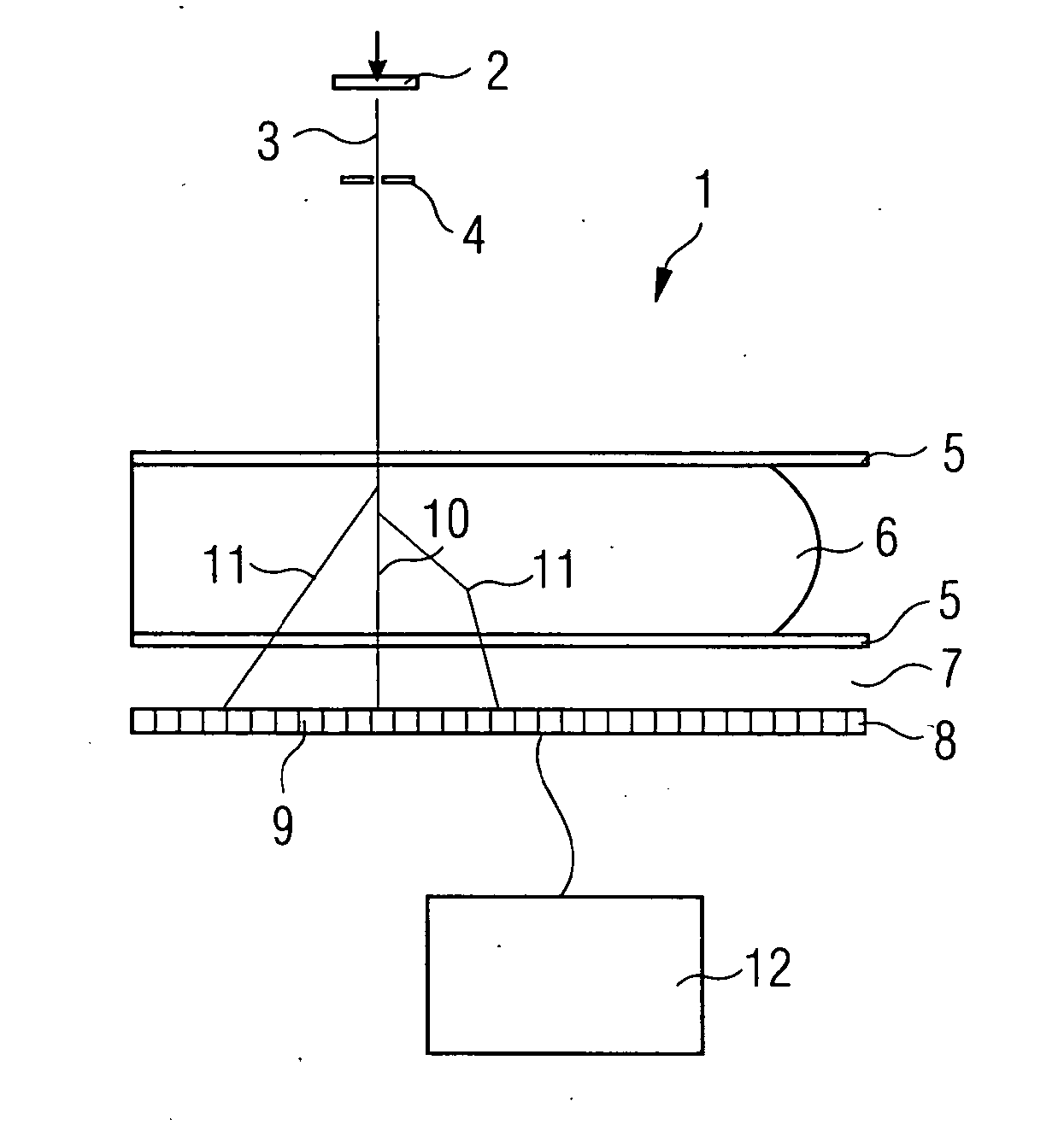
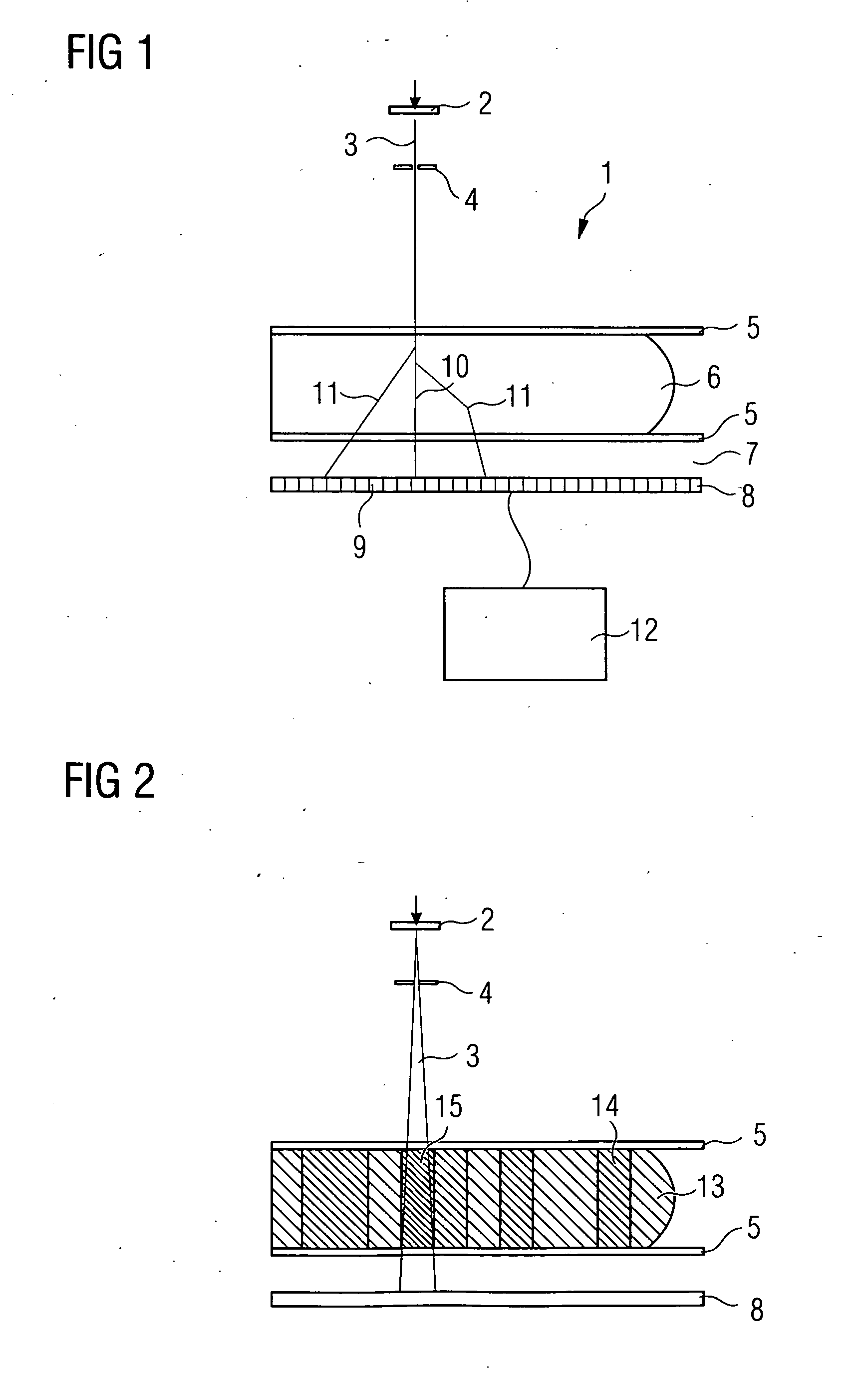
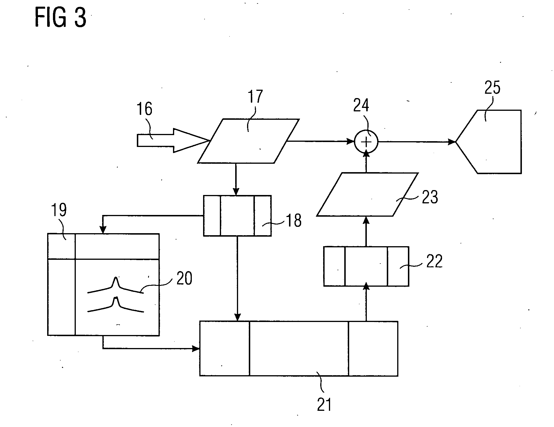
[0115] In this example, scatter correction is performed, as described above with equations (#5)-(#9) and (#13)-(#15), using homogeneous location-dependent scatter beam spread functions 20 (=SBSF). For creating said scatter beam spread functions 20 it is assumed by way of simplification that the tissue distribution characterized by the proportion α(j, k) of glandular tissue along the beam leading from the source to the detector pixel continues in a constantly homogeneous manner according to FIG. 4 at right angles to the beam, i.e. parallel to the compression plates 5. It is therefore assumed with respect to the scatter contribution of the beam in the pixel (j, k) that the tissue composition in the lateral neighborhood of the beam does not vary abruptly. Although this is no longer relevant at the edge of the breast, special treatment could be provided there.

[0116] Note, however, that the actual location-dependent inhomogeneity of the tissue composition is allowed for by a specificall...

example 1a

[0117] In this example 1a the method is essentially performed as in example 1.

[0118] However, the following simplifications are made:

[0119] For each pre-specified layer thickness and the other parameters such as voltage and pre-filtering, a common SBSF 20 is used for all the pixels. In this case the SBSF 20 is therefore selected on a location-independent basis. The selection can be made, for example, by suitable averaging over the tissue compositions present. ΔS in equation (#7) and (#9) then becomes independent of the pixel index (j, k); the double index (j, k) can—similarly as in equations (#16a) to (#16c)—be omitted.

[0120] The important feature is that the integral in equation (#9) becomes a genuine convolution which can be efficiently executed by FFT (=Fast Fourier Transformation).

example 1b

[0121] In this example 1b the method is likewise performed essentially as in example 1.

[0122] In this case, however, a uniform convolution kernel (for all the layer thicknesses) is used for the scatter calculation. The fact that for a small layer thickness relatively less scatter is produced than for a large layer thickness must be taken into account by means of scaling factors which are a function of the layer thickness and other parameters such as voltage and filtering.

[0123] Approximately the same computational complexity is necessary for example 1b as for example 1a. On the other hand, much less memory space is required for storing the breast SBSF atlas 19 in this example.


PUM


Abstract

An apparatus for projection radiography is set up for correcting stray radiation. The apparatus comprises an evaluation unit which evaluates the distribution of stray radiation, which is arranged in a tabular manner in a data memory, for correcting stray radiation, said distribution being initially determined with the aid of Monte-Carlo-Simulation which takes into account multiple interactions of the photons with the object which is to be analyzed.

Description

CROSS REFERENCE TO RELATED APPLICATIONS [0001] This application is the US National Stage of International Application No. PCT / EP2005 / 052744, filed Jun. 14, 2005 and claims the benefit thereof. The International Application claims the benefits of German application No. 10 2004 029 010.5 DE filed Jun. 16, 2004, both of the applications are incorporated by reference herein in their entirety.FIELD OF INVENTION [0002] The invention relates to an apparatus for projection radiography comprising a radiation source, a detector and, downstream of said detector, a processing unit which uses the projection data supplied by the detector to approximately determine the scatter material distribution of the object under examination and which reads out scatter information from a data memory as a function of the scatter material distribution and corrects the projection data in respect of the scatter component on the basis of said scatter information. [0003] The invention further relates to a method wi...

Claims


Application Information

Patent Timeline
IPC IPC(8): G06T5/00A61B6/00A61B6/02
CPCA61B6/027A61B6/4035A61B6/482G06T2207/10116G06T2207/30068A61B6/4291G06T5/003A61B6/502G06T5/73
Inventor RUHMSCHOPF, ERNST-PETER
Owner SIEMENS HEATHCARE GMBH
Learn More