
Measurement method, measurement unit, processing unit, pattern forming method , and device manufacturing method

a technology of measurement method and measurement unit, applied in the direction of measurement device, photomechanical treatment, instruments, etc., can solve the problems of difficult wafer surface adjustment, high cost, and long hours of adjustment, and achieve the effect of improving the productivity of the devi

Inactive Publication Date: 2008-01-17
NIKON CORP
View PDF7 Cites 17 Cited by
  • Summary
  • Abstract
  • Description
  • Claims
  • Application Information

AI Technical Summary

Benefits of technology

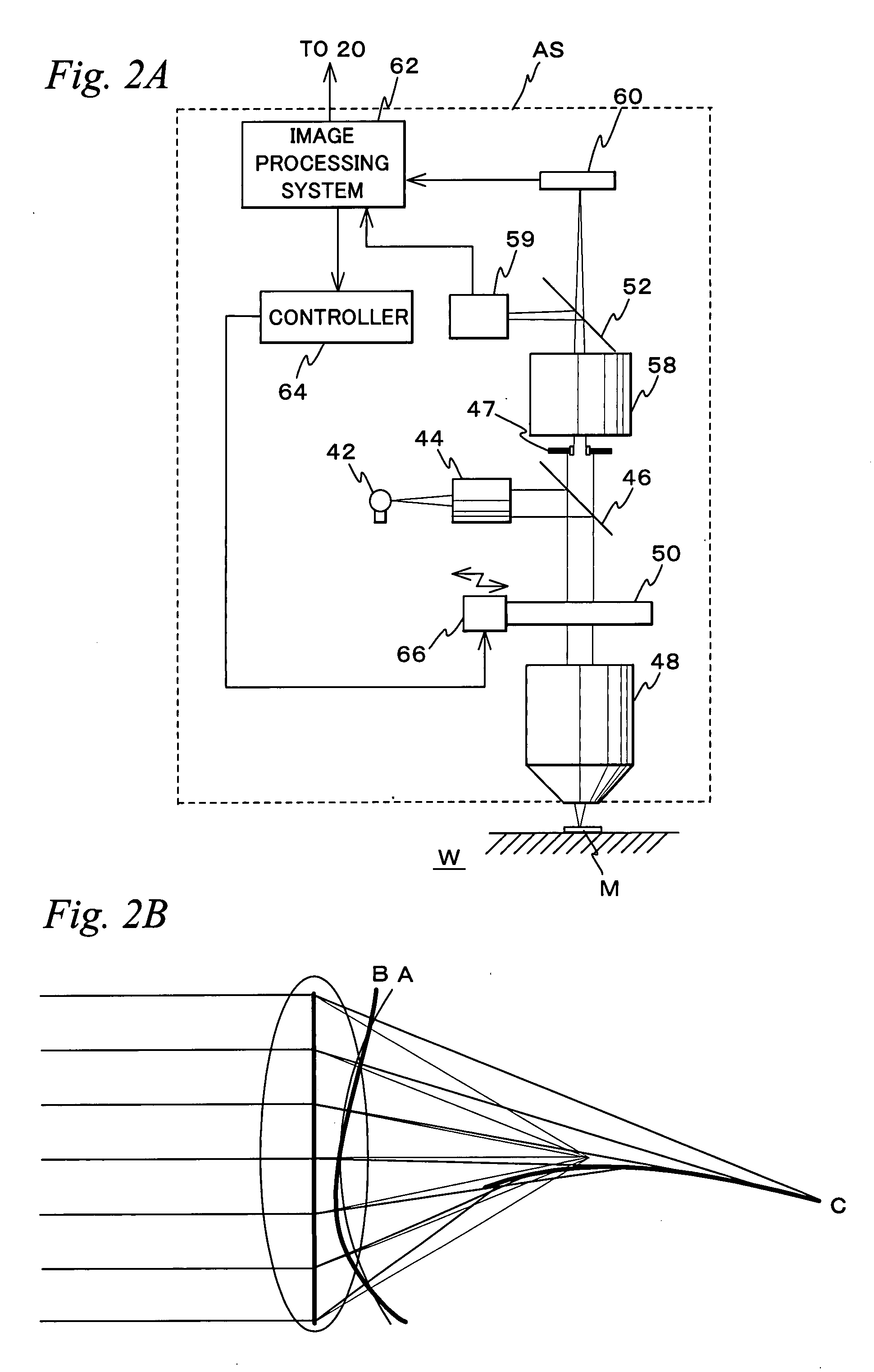
[0009] According to this method, the mark is measured in an incoherent state where the ratio of the numerical aperture of the illumination optical system to the numerical aperture of the light condensing optical system is set to one or more, and the mark is also detected based on an electrical signal whose light of an even order diffraction which is the cause of noise component is reduced. Therefore, change in measurement error of the mark position caused by a complex effect of aberration in the light condensing optical system and defocus or a complex effect of the individual difference of the mark and defocus is reduced, and it becomes possible to measure the positional information with high precision.
[0025] According to this method, it becomes possible to improve productivity of a device.

Problems solved by technology

However, in general, adjusting the aberration itself of the objective lens is costly and also requires long hours.
Further, because it is extremely difficult to reduce the aberration completely to zero, mark measurement has to be performed while anticipating positional shift of the mark due to the aberration.
However, in the case where the mark measurement position shifts greatly due to defocus, it is physically difficult to adjust the wafer surface and perform focusing of each of the four points on the wafer simultaneously with each eye, and simultaneous measurement of four or more of the marks was virtually impractical.

Method used


Image

  • Measurement method, measurement unit, processing unit, pattern forming method , and device manufacturing method
  • Measurement method, measurement unit, processing unit, pattern forming method , and device manufacturing method
  • Measurement method, measurement unit, processing unit, pattern forming method , and device manufacturing method

Examples


Embodiment Construction

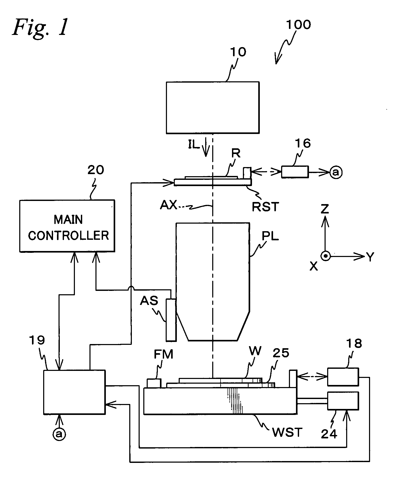
[0054] Hereinafter, an embodiment of the present invention will be described, referring to FIGS. 1 to 23. FIG. 1 shows an entire view of an arrangement of an exposure apparatus 100 to which the measurement method related to the embodiment can be suitably applied. Exposure apparatus 100 is a projection exposure apparatus by the step-and-scan method. Exposure apparatus 100, which is shown in FIG. 1, is equipped with an illumination system 10, a reticle stage RST that holds a reticle R, a projection optical system PL, a wafer stage WST that holds a wafer W, an alignment system AS that measures a mark on wafer W, and a control system or the like for such sections.

[0055] Illumination system 10 is configured similar to the illumination system disclosed in, for example, Kokai (Japanese Unexamined Patent Application Publication) No. 2001-313250 (corresponding U.S. Patent Application Publication No. 2003 / 0025890 description) or the like. More specifically, illumination system 10 emits a coh...


PUM


Abstract

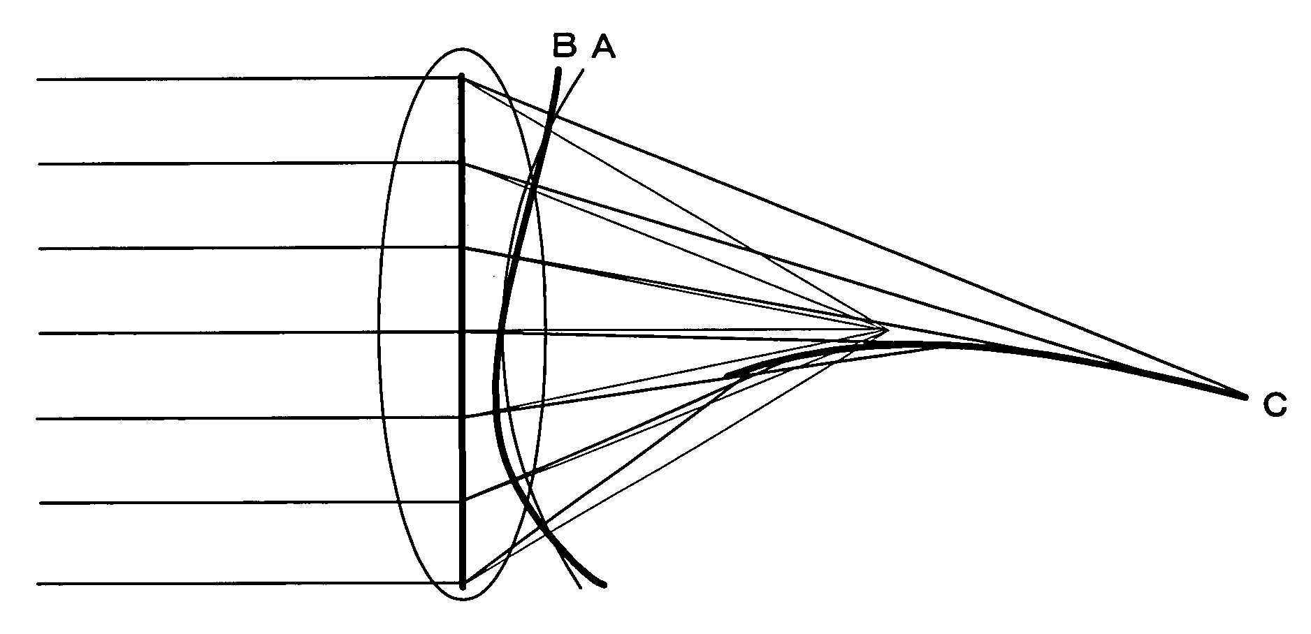
A coherence factor σ of an alignment system is set to 1 or more, and positional information of a mark is detected from a photodetection signal that corresponds to the mark intensity image of the mark due to a zero order light and light of an odd order diffraction from the mark. When σ≧1, a beam pair of a zero order light and a light of +1st order diffraction appears without fail with respect to a beam pair of a zero order light and a light of −1st order diffraction that pass through the same two points on the pupil plane and the positional shift of the mark image caused by both pairs is canceled out, and by the change in mark step or aberration, the change in mark position shift amount is reduced. Accordingly, the mark can be detected with high precision.

Description

BACKGROUND OF THE INVENTION [0001] 1. Field of the Invention [0002] The present invention relates to measurement methods, measurement units, processing units, pattern forming methods, and device manufacturing methods, and more specifically to a measurement method that uses that uses a detection unit which is equipped with an illumination optical system that irradiates an illumination light on a mark formed on an object, a light converging optical system that converges diffracted light from the mark irradiated by the illumination light, and a photoelectric conversion unit which converts the converged light into electrical signals, a measurement unit that uses the measurement method, a processing unit that is equipped with the measurement unit, a pattern forming method that uses the measurement method, and a device manufacturing method that uses the pattern forming method. [0003] 2. Description of the Related Art [0004] In position setting (alignment) of a substrate such as a wafer or...

Claims


Application Information

Patent Timeline
IPC IPC(8): G01B11/00
CPCG03F9/7026G03F9/7088G03F9/7049
Inventor HAGIWARA, TSUNEYUKI
Owner NIKON CORP
Learn More