Equivalent time sampling system

a sampling system and equivalent time technology, applied in the field of equal time sampling and optical time domain reflectometer, can solve the problems of high speed of delay circuit, inability to sample in real time, and inability to calibrate precision parts and also require high speed

Active Publication Date: 2008-01-17
JOHN FLUKE MFG CO INC
View PDF3 Cites 17 Cited by
  • Summary
  • Abstract
  • Description
  • Claims
  • Application Information

AI Technical Summary

Problems solved by technology

Practical ADCs cannot sample that quickly in real time.
However, in such an implementation, the delay circuit requires high speed, precision parts and also must be calibrated to account for component variations, and is subject to temperature induced inaccuracy.
Some drawbacks of the prior art scheme include:
Calculating DAC values to create the interlacing of samples is prone to some problems in that the delay is create

Method used


Image

  • Equivalent time sampling system
  • Equivalent time sampling system
  • Equivalent time sampling system

Examples


example

[0035

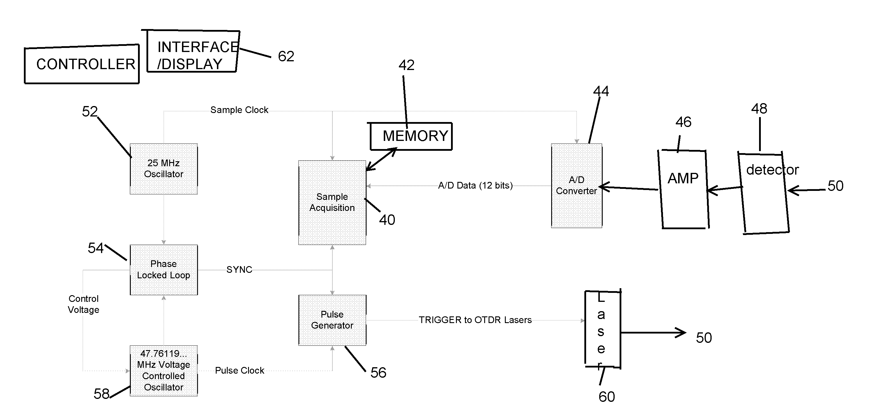
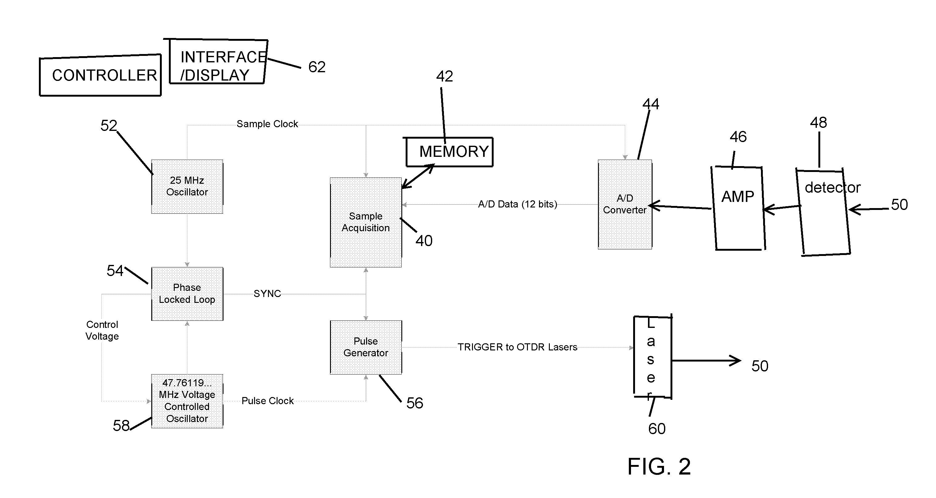
[0036]If the sample clock is 25 MHz, and Ns=128, then:

Ts=40 ns=Ns×Tq=128×(0.3125 ns)

[0037]The set of even divisors of 128, (available step sizes as multiples of minimum step), is:

[0038]1 2 4 8 16 32 64 128

[0039]This is the set of available trace time steps, in units of 0.3125 ns. Note that if desired, non-binary, more closely spaced time steps can be obtained by choosing a suitable Ns, such as the superabundant number 120. This number has divisors:

1 2 3 4 5 6 8 10 12 15 20 24 30 40 60 120

[0040]Next, we choose the pulse clock period. Like the sample clock period, the pulse clock period must be an integer number of minimum time steps:

Tp=Np×Tq

[0041]The pulse clock period and sample clock period, in units of minimum time steps, should have no common divisors other than 1, to obtain all the available time steps. This is always true if Np is prime, however primeness is not necessary.

[0042]Np and Ns must have no common divisors

[0043]Continuing the example, with Ns=128, we can choose ...


PUM


Abstract

An equivalent time sampling system employs two clock frequency sources, phase locked, wherein an analog to digital converter sampling clock is derived from one source and a pulse generator clock is derived from the other. Choice of the clock frequencies determines minimum time step and the set of available time steps, and pulse repetition period determines the time step size, for equivalent time sampling. The system is suitably implemented in a time domain reflectometer, optical time domain reflectometry system, or other systems for obtaining time domain responses to a periodic stimulus of a system under test, with stimulus rate and the sampling intervals varying over a wide range.

Description

BACKGROUND OF THE INVENTION[0001]This invention relates to test and measurement instruments, and more particularly to equivalent time sampling and, for example, to an optical time domain reflectometer (OTDR) that employs an improved equivalent time sampling system.[0002]An OTDR is an optical fiber test instrument that launches light pulses into a fiber, then measures the back reflected light signals as a function of time. By examining the result, useful information such as location and loss of connectors and fiber length can be determined.[0003]With reference to FIG. 1, a block diagram of an OTDR in accordance with the prior art, Some of the typical functional blocks in an OTDR include:[0004]Laser diode light source 12, pulsed current source for laser 14, photodiode light receiver 16, fiber directional coupler 18, amplifiers 20, analog to digital converter (ADC) 22, acquisition timing comprising a pulse trigger 24 and ADC clock 26, memory for trace acquisition 28, controller (Digita...

Claims


Application Information

Patent Timeline
IPC IPC(8): G01N21/00
CPCG01M11/3145
Inventor BOTTMAN, JEFFREY S.GESSAMAN, WILLIAM K.
Owner JOHN FLUKE MFG CO INC
Why Eureka
Try Eureka