
Methods and systems for manufacturing optimized concrete

a technology of optimizing and manufacturing methods, applied in the field of concrete composition design optimization, can solve the problem that hydraulic cement is not able to realize the highest theoretical binding efficiency at lower strengths, and achieve the effect of less trial and error testing, more accurate predictions of concrete strength, and efficient identification

Inactive Publication Date: 2008-01-10
ICRETE LLC
View PDF42 Cites 18 Cited by
  • Summary
  • Abstract
  • Description
  • Claims
  • Application Information

AI Technical Summary

Benefits of technology

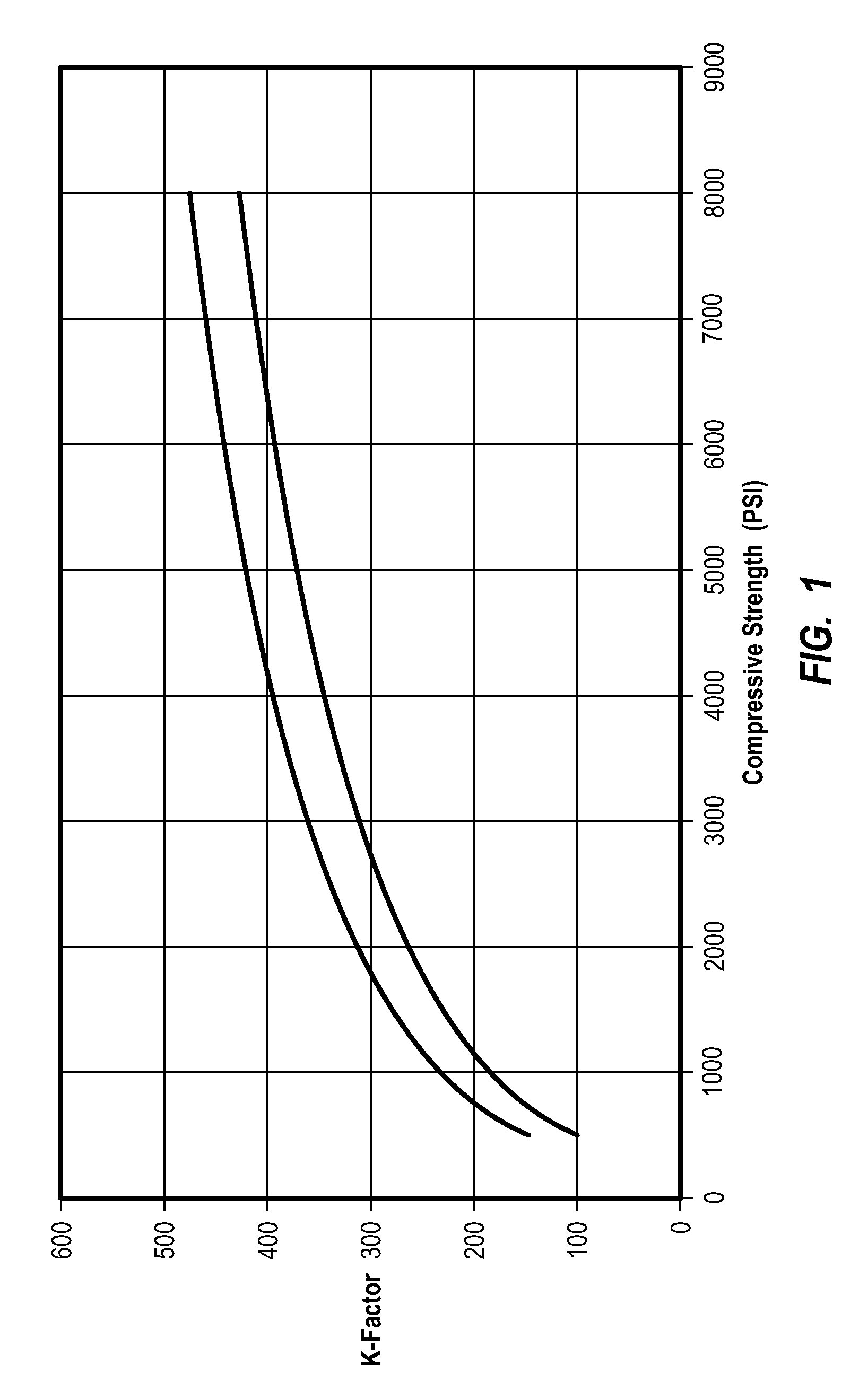
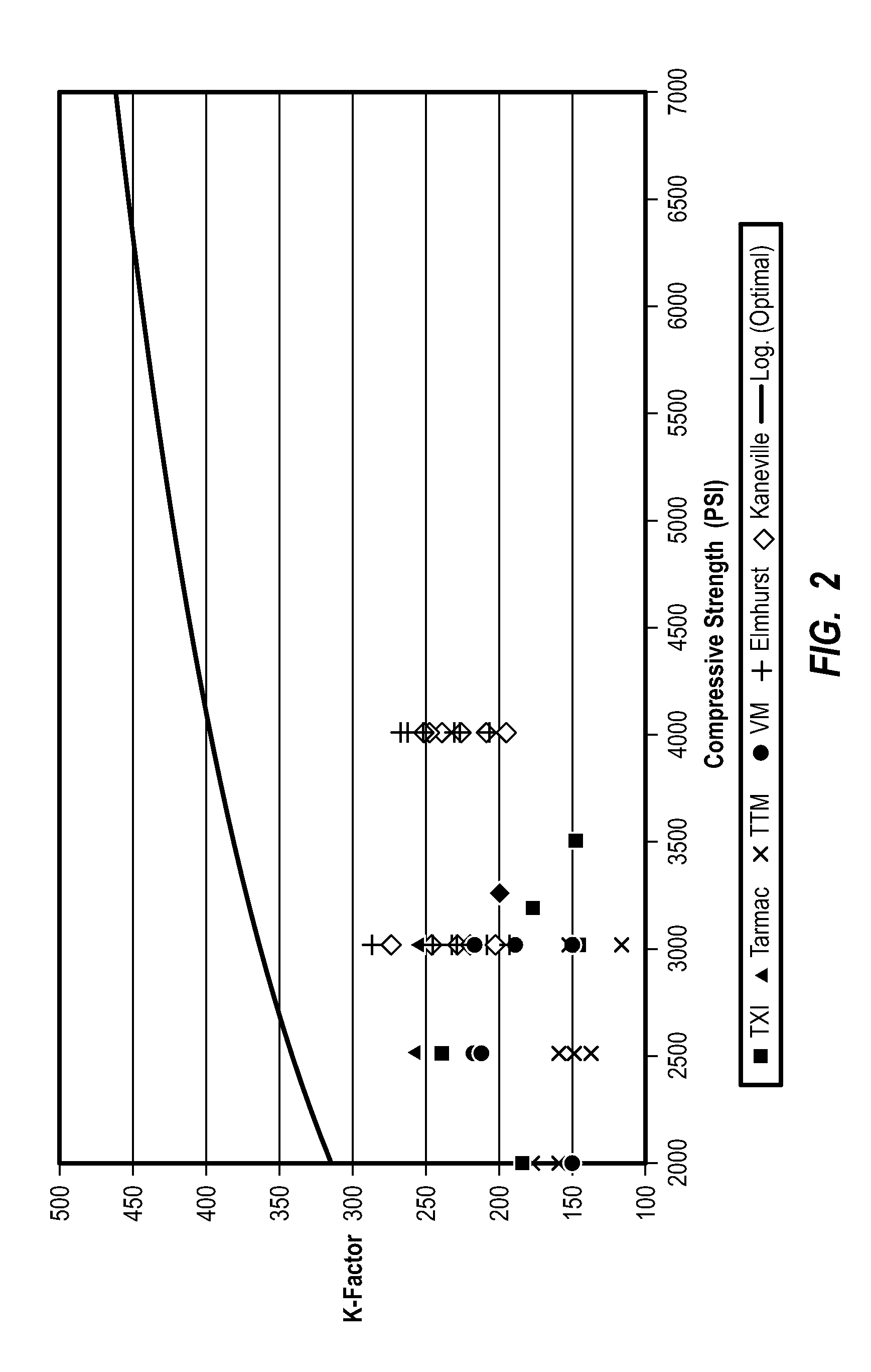
[0026] It has now been discovered that the constant K (or “K factor”) within Feret's strength equation is not a constant but varies depending on the efficiency with which hydraulic cement is able to bind or glue the aggregate particles together. That is true even if the mixing apparatus, aggregate strength, and other factors that affect strength are kept constant. The K factor, which dynamically varies with the binding efficiency of the hydraulic cement binder, can be empirically determined based on concrete strength. Knowing the dynamic variability of the K factor allows for more accurate predictions of concrete strength when performing a design optimizing procedure compared to an optimization procedure that assumes the K factor remains constant so long as the mixing apparatus and raw materials also remain constant. The inventive optimization procedure (hereinafter “improved DOC process”) efficiently identifies one or more optimized mix designs with less trial and error testing since using the correct K factor in the first instance naturally reduces the need to correct for errors that would otherwise arise by using an incorrect K factor to predict concrete strength.

Problems solved by technology

This indicates that hydraulic cement is not able to realize its highest theoretical binding efficiency at lower strengths, but only approaches it at higher strengths.

Method used


Image

  • Methods and systems for manufacturing optimized concrete
  • Methods and systems for manufacturing optimized concrete
  • Methods and systems for manufacturing optimized concrete

Examples


examples 1-4

[0313] Examples 1-4 illustrate four optimized concrete mix designs that were prepared using the improved DOC process described herein. The four mix designs of Examples 1-4 can replace twelve pre-existing standard concrete mix designs utilized by an existing concrete manufacturing plant. Each mix design of Examples 1-4 corresponds to a group of three pre-existing mix designs of similar type that guarantee a minimum compressive strength, at a specified slump, and percentage of entrained air when delivered to the customer. The pre-existing mix designs of the concrete manufacturing plant, their components, cost (revised Apr. 7, 2006), and apparent design K factors, will be presented in four groups of three concrete mix designs, each group having similar properties or characteristics.

examples 5-8

[0322] Examples 5-8 illustrate four optimized concrete mix designs that were prepared using the improved DOC process described herein. The four mix designs of Examples 5-8 can replace twelve pre-existing standard concrete mix designs of an existing concrete manufacturing plant, which used the same 12 mix designs as in Comparative Examples 1a-4c but manufactured concrete using a different set of raw materials. Each mix design of Examples 5-8 corresponds to a group of three pre-existing mix designs of similar type that guarantee a minimum compressive strength, at a specified slump, and percentage of entrained air when delivered to the customer. The pre-existing mix designs of the concrete manufacturing plant, their components, cost (revised Oct. 27, 2005), and apparent design K factors, will be presented in four groups of three concrete mix designs, each group having similar properties or characteristics.

examples 9-12

[0330] Examples 9-12 illustrate four optimized concrete mix designs that were prepared using the improved DOC process described herein. The four mix designs of Examples 9-12 can replace twelve pre-existing standard concrete mix designs of an existing concrete manufacturing plant, which used the same 12 mix designs as in Comparative Example 1a-4c but manufactured concrete using a different set of raw materials. Each mix design of Examples 9-12 corresponds to a group of three pre-existing mix designs of similar type that guarantee a minimum compressive strength, at a specified slump, and percentage of entrained air when delivered to the customer. The pre-existing mix designs of the concrete manufacturing plant, their components, cost (revised Oct. 27, 2005), and apparent design K factors, will be presented in four groups of three concrete mix designs, each group having similar properties or characteristics.


PUM

PropertyMeasurementUnit
diametersaaaaaaaaaa
diameter sizeaaaaaaaaaa
TOTAL⁢ ⁢POROSITYaaaaaaaaaa

Abstract

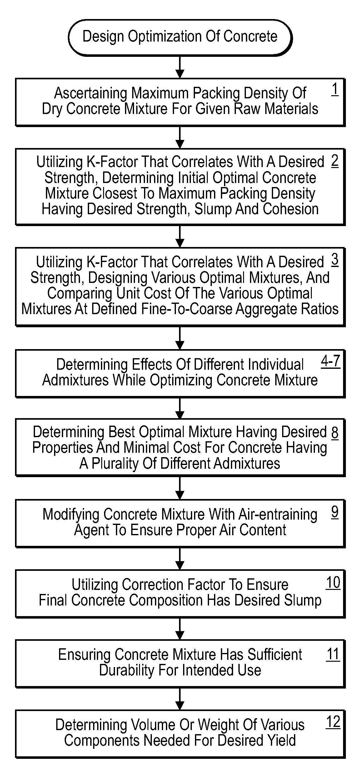
Design optimization methods can be used to design concrete mixtures having optimized properties, including desired strength and slump at minimal cost. The design optimization methods use a computer-implemented process that is able to design and virtually “test” millions of hypothetical concrete compositions using mathematical algorithms that interrelate a number of variables that affect strength, slump, cost and other desired features. The design optimization procedure utilizes a constant K (or K factor) within Feret's strength equation that varies (e.g., logarithmically) with concrete strength for any given set of raw material inputs and processing equipment. That means that the binding efficiency or effectiveness of hydraulic cement increases with increasing concentration so long as the concrete remains optimized. The knowledge of how the K factor varies with binding efficiency and strength is a powerful tool that can be applied in multiple circumstances. A concrete manufacturing process may include accurately measuring the raw materials to minimize variation between predicted and actual strength, as well as carefully controlling water content throughout the manufacturing and delivery process.

Description

CROSS-REFERENCE TO RELATED APPLICATION [0001] This application is a division of U.S. application Ser. No. 11 / 471,293, filed Jun. 19, 2006, which claims the benefit under 35 U.S.C. § 119(e) of U.S. Provisional Application Ser. No. 60 / 691,916, filed Jun. 17, 2005. This application also claims the benefit of earlier filed and co-pending International Application No. PCT / US06 / 23863, filed Jun. 19, 2006. The disclosures of the foregoing applications are incorporated herein in their entirety.BACKGROUND OF THE INVENTION [0002] 1. The Field of the Invention [0003] The invention is in the field of concrete compositions, more particularly in the design-optimization of concrete compositions based on factors such as performance and cost. The invention more particularly relates to the design and manufacture of concrete using improved methods that more efficiently utilize all the components from a performance and cost standpoint and minimize strength variability, as well as unique methods for red...

Claims


Application Information

Patent Timeline
Patent Type & Authority Applications(United States)
IPC IPC(8): G06F19/00
CPCC04B28/02G06F17/5004G06F17/5009G06F2217/04G06F2217/08C04B14/06C04B18/08C04B18/146C04B24/12C04B40/0096C04B2103/302C04B2103/304G06F30/13G06F30/20G06F2111/02G06F2111/06Y02W30/91
Inventor ANDERSEN, PER JUSTHODSON, SIMON K.
Owner ICRETE LLC
Learn More