
Tandem Organic Electroluminescent Element and Use of the Same

a technology of organic electroluminescent elements and organic electroluminescent elements, which is applied in the direction of discharge tube/lamp details, luminescent screen of discharge tube, natural mineral layered products, etc., can solve the problems of poor reproducibility, and poor transparency, and achieve high transparency, weakened carrier injection ability, and high carrier transport rate

Inactive Publication Date: 2008-01-10
AU OPTRONICS CORP
View PDF23 Cites 4 Cited by
  • Summary
  • Abstract
  • Description
  • Claims
  • Application Information

AI Technical Summary

Benefits of technology

[0012]An object of this invention is to provide a tandem organic electroluminescent element. The tandem organic electroluminescent element comprises an anode, a cathode, a first organic electroluminescent unit, a second organic electroluminescent unit, and a connecting layer. The first organic electroluminescent unit is disposed between the anode and the cathode. The second organic electroluminescent unit is disposed between the anode and the cathode. The connecting layer is disposed between the first unit and the second unit. The connecting layer comprises a bipolar organic compound and a conductive dopant. The connecting layer has high transparency and a high carrier transport rate. The tandem organic electroluminescent element including the connecting layer can improve the following problems: crosstalk, weakened carrier injection ability, bad reproducibility resulting from overly thin metal, bad transparency, and / or lateral electricity leakage. The luminous efficiency of the element would be improved thereby.
[0013]Another object of this invention is to provide an organic electroluminescent display. The organic electroluminescent display comprises the tandem organic electroluminescent element as recited above. With this tandem organic electroluminescent element, crosstalk, weakened carrier injection ability, bad reproducibility resulting from overly thin metal, bad transparency, and / or easily lateral electricity leakage would be improved. The tandem organic electroluminescent element according to the present invention has high transparency and a high carrier transport rate which farther improves the interior luminous efficiency of a display comprising the element.

Problems solved by technology

The tandem organic electroluminescent element including the connecting layer can improve the following problems: crosstalk, weakened carrier injection ability, bad reproducibility resulting from overly thin metal, bad transparency, and / or lateral electricity leakage.

Method used


Image

  • Tandem Organic Electroluminescent Element and Use of the Same
  • Tandem Organic Electroluminescent Element and Use of the Same
  • Tandem Organic Electroluminescent Element and Use of the Same

Examples


first embodiment

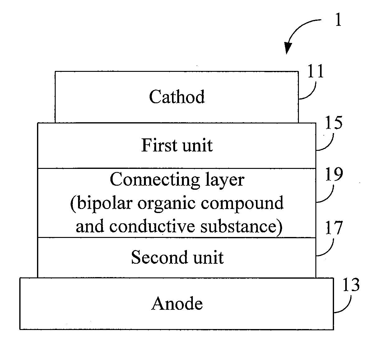
[0022]FIG. 1 shows a tandem organic electroluminescent element according to the present invention. The tandem organic electroluminescent element 1 comprises a cathode 11, an anode 13, a first organic electroluminescent unit 15, a second organic electroluminescent unit 17, and a connecting layer 19. The first unit 15 and the second unit 17 are disposed between the cathode 11 and the anode 13, and the connecting layer 19 is disposed between the first unit 15 and the second unit 17.

[0023]For a tandem organic electroluminescent element 1, the anode 13 comprises material(s) with relatively high work function, and the cathode 11 comprises material(s) with relatively low work function. The limitations of the electrodes are that one of the cathode 11 and the anode 13 is a transparent electrode, and the other is either a transparent electrode or an opaque electrode. For example, ITO may be used as the material of the transparent electrode as the anode 13, and materials, such as magnesium, ma...

second embodiment

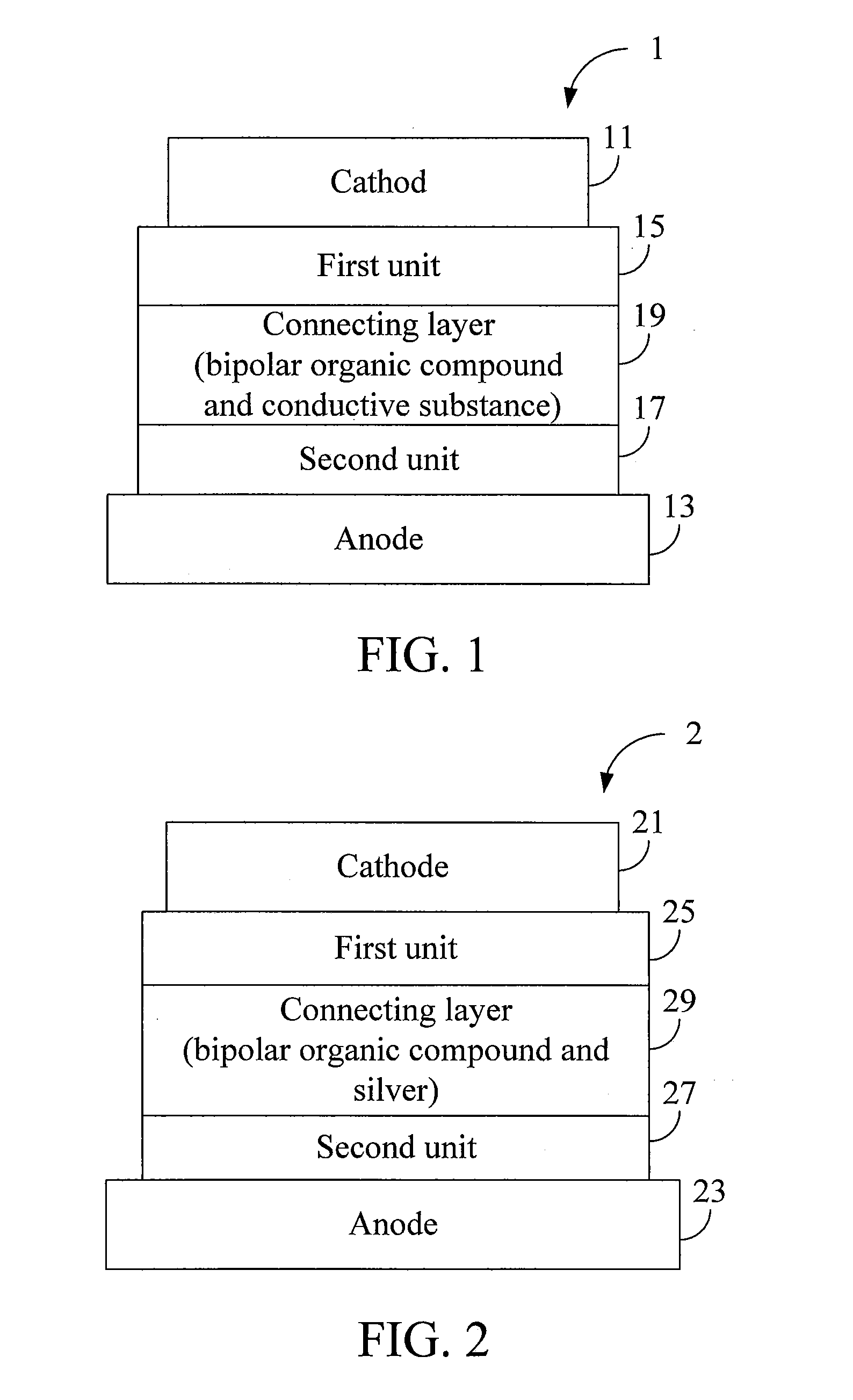
[0028]FIG. 2 shows a tandem organic electroluminescent element according to the present invention. The tandem organic electroluminescent element 2 comprises a cathode 21, an anode 23, a first organic electroluminescent unit 25, a second organic electroluminescent unit 27, and a connecting layer 29. The first unit 25 and the second unit 27 are disposed between the cathode 21 and the anode 23, and the connecting layer 29 is disposed between the first unit 25 and the second unit 27. The connecting layer 29 comprises a bipolar organic compound, and a conductive dopant. The bipolar organic compound is MADN, while the conductive dopant is silver as shown in FIG. 2. Preferably, the concentration of silver in the connecting layer 29 ranges from 10% to 60%, and more preferably from 20% to 50%.

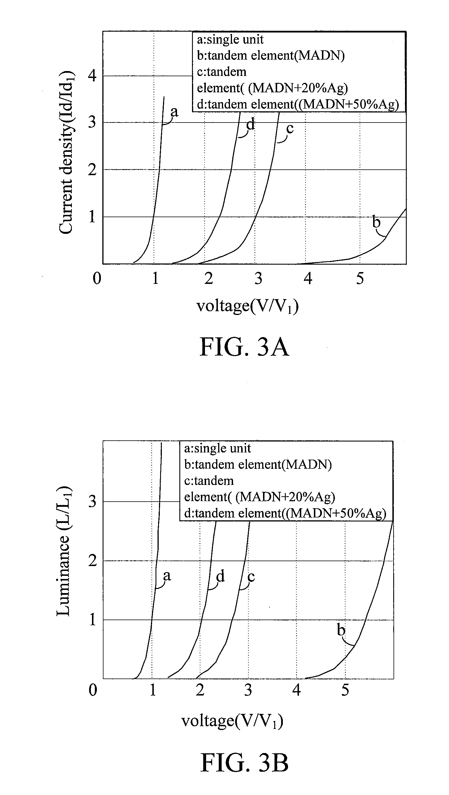
[0029]The efficacy of the tandem organic electroluminescent element 2 is shown in FIG. 3A to FIG. 3D. FIG. 3A shows a voltage-current density relationship in graphic form. The horizontal axis and the lo...

third embodiment

[0033]the present invention is an organic electroluminescent display. The organic electroluminescent display comprises a plurality of tandem organic electroluminescent elements as recited above and a plurality of substrates. The substrate comprises a plurality of thin film transistors, wherein the plurality of thin film transistors are electrically connected to a plurality of electrodes of the tandem organic electroluminescent elements. With this tandem organic electroluminescent element, crosstalk, weakened carrier injection ability, bad reproducibility resulting from overly thin metal, bad transparency, and / or lateral electricity leakage would be improved. The present invention has high transparency and a high carrier transport rate which further improves the interior luminous efficiency of the display.


PUM

PropertyMeasurementUnit
work functionaaaaaaaaaa
carrier mobilityaaaaaaaaaa
conductiveaaaaaaaaaa

Abstract

A tandem organic electroluminescent element for use in an organic electroluminescent display is provided. The organic electroluminescent element comprises an anode, a cathode, a first organic electroluminescent unit, a second organic electroluminescent unit, and a connecting layer. Both the first organic electroluminescent unit and the second organic electroluminescent unit are disposed between the anode and the cathode. The connecting layer is between the first and second units, and comprises a bipolar organic compound and a conductive dopant.

Description

[0001]This application claims the benefit from the priority of Taiwan Patent Application No. 095124970 filed on Jul. 7, 2006.BACKGROUND OF THE INVENTION[0002]1. Field of the Invention[0003]The present invention relates to a tandem organic electroluminescent element, and more particularly, to a tandem organic electroluminescent element for use in an organic electroluminescent display.[0004]2. Descriptions of the Related Art[0005]Because organic electroluminescent devices are known for their high brightness, high, contrast, thinness, wide temperature range, lightness, self-luminosity, unlimited viewing angle, easy manufacturing process and high response rate, they have become an important field in worldwide technology development. These devices also consume low levels of power, lack a need for a backlight source and have no viewing angle limitation. The flat panel display industrial field adds great importance to the organic electroluminescent devices. There are two types of technolog...

Claims


Application Information

Patent Timeline
Patent Type & Authority Applications(United States)
IPC IPC(8): H01L51/52H01L51/54
CPCH01L51/5278H01L51/5052H10K50/155H10K50/19
Inventor LEE, CHUNG-CHUNLI, HSING-CHUAN
Owner AU OPTRONICS CORP
Learn More