Electromagnetic device
a technology of electromagnetic devices and eddy current, which is applied in the direction of windings, communication cables, cables, etc., can solve the problems of large eddy current generation, insufficient effect of reducing eddy current loss, and large number of split conductors, so as to reduce the eddy current loss and reduce the filling factor
- Summary
- Abstract
- Description
- Claims
- Application Information
AI Technical Summary
Benefits of technology
Problems solved by technology
Method used
Image
Examples
first embodiment
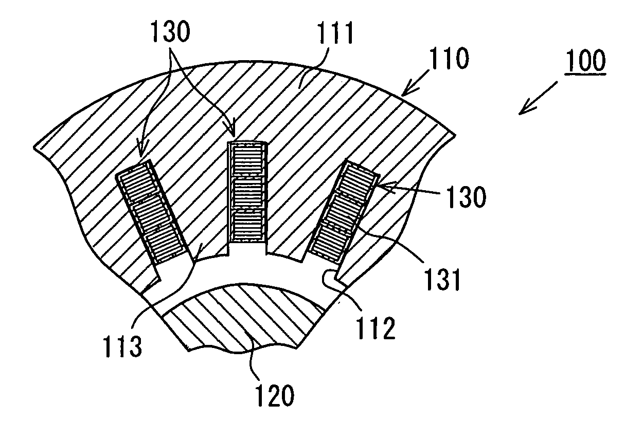
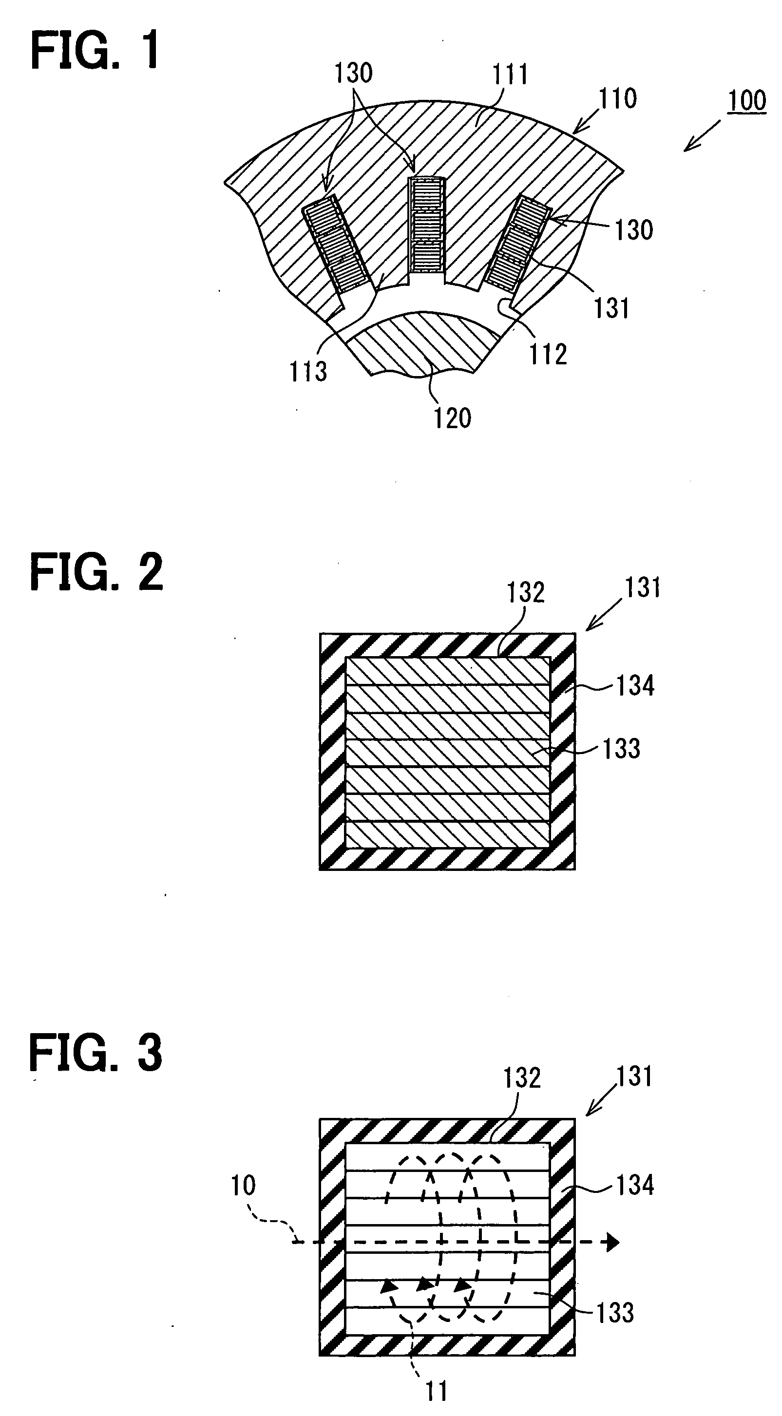
[0064]As illustrated in FIG. 1, a plurality of coils 130 in three phases are wound on a stator 110 of a motor 100, which has a rotor 120. In a core 111 constructing the stator 110, there are formed a plurality of slots 112, and the coils 130 equivalent to three phases (U phase, V phase, and W phase) are housed in these slots 112. The stator 110 has a plurality of teeth 113 between the two slots 112. Each coil 130 is constructed by lap-wound windings 131 in three layers. Each winding 131 corresponds to a conductor.
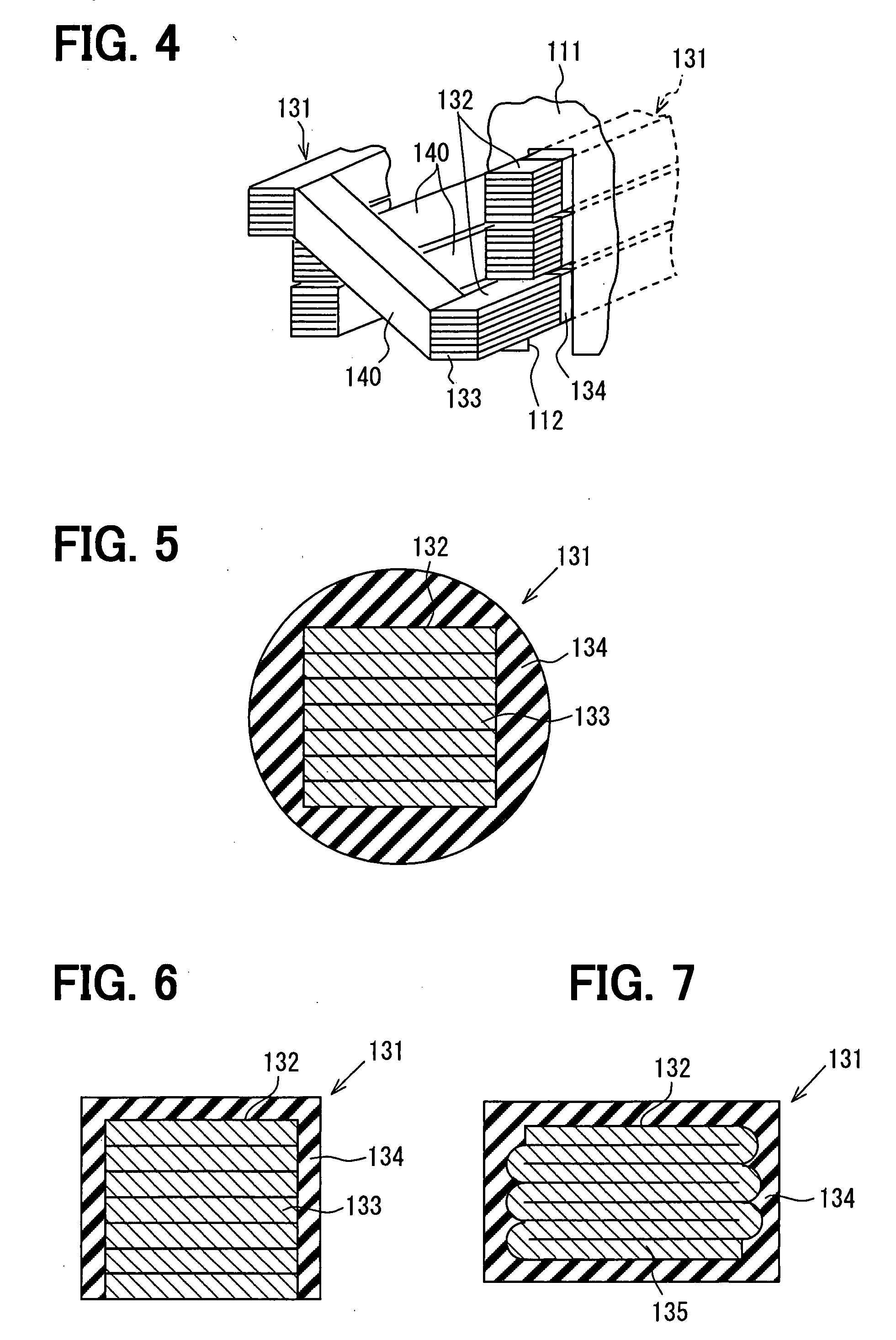
[0065]As illustrated in FIG. 2, the winding 131 has a conductor stack 132 as a portion to which at least a leakage flux is linked (portion housed in the slot 112). The winding 131 in a rectangular sectional shape may be changed to different sectional shape. The sectional dimensions of the windings 131 vary depending on usage. For a motor of specifications (motor diameter: 300 mm, motor output: 10 to 50 kW or so) for use in a power source for hybrid electric vehicles, for ex...
second embodiment
[0081]In the second embodiment, as illustrated in FIG. 8, the outer insulating member 134 is disposed on the outer circumferential surface of the conductor stack 132 that forms at least part of the winding 131. In addition, an inner insulating member 136 is disposed between stack planes of the connecting two conductor constructional elements 133.
[0082]There is no special restriction on the constituent material of the inner insulating member 136. This embodiment adopts adhesive (e.g., epoxy adhesive or cyanoacrylate adhesive) for bonding and fixing together conductor constructional elements 133 divided into a plurality of pieces. When adhesive is adopted as the inner insulating member 136, it is possible to fix together a plurality of conductor constructional elements 133 and further reduce eddy-current loss. Therefore, in case the conductor constructional elements 133 are fixed together, the construction can be simplified.
[0083]In one and the same winding 131, the thickness t2 of th...
third embodiment
[0088]In the third embodiment, as illustrated in FIG. 10, the winding 131 including the conductor stack 132 of the first embodiment or second embodiment is adopted only for some of the windings that respectively construct a plurality of coils 130.
[0089]Specifically, the motor 100 includes two coils 130a, 130b formed by winding windings 131 on the core 111 of the stator 110 in opposite directions. Two coils 130a, 130b are electrically connected together to construct a coil unit. It is known that, when coils 130a, 130b different from each other in the winding direction are wound in two layers on the core 111, leakage fluxes 10 are separately linked to the individual coils 130a, 130b. Therefore, eddy-current loss can be reduced in one coil unit. With this construction, of two coils 130a, 130b, the coil 130a on which a leakage flux 10 is more strongly exerted is constructed of the winding 131 of the construction of the first or second embodiment. This coil is positioned on the radially ...
PUM
| Property | Measurement | Unit |
|---|---|---|
| eddy-current loss | aaaaa | aaaaa |
| diameter | aaaaa | aaaaa |
| thickness | aaaaa | aaaaa |
Abstract
Description
Claims
Application Information
 - R&D
- Intellectual Property
- Life Sciences
- Materials
- Tech Scout
- Unparalleled Data Quality
- Higher Quality Content
- 60% Fewer Hallucinations
Browse by: Latest US Patents, China's latest patents, Technical Efficacy Thesaurus, Application Domain, Technology Topic, Popular Technical Reports.
© 2025 PatSnap. All rights reserved.Legal|Privacy policy|Modern Slavery Act Transparency Statement|Sitemap|About US| Contact US: help@patsnap.com


