
Anticorrosion device for hydraulic cylinder in heavy construction equipment

a technology of anti-corrosion device and hydraulic cylinder, which is applied in the direction of engine seals, springs, vibration dampers, etc., can solve the problems of weak sealing reliability, weak packing force of rib parts in the groove of the head cover, and relatively worse sealing reliability

Inactive Publication Date: 2008-01-10
VOLVO CONSTR EQUIP
View PDF8 Cites 11 Cited by
  • Summary
  • Abstract
  • Description
  • Claims
  • Application Information

AI Technical Summary

Benefits of technology

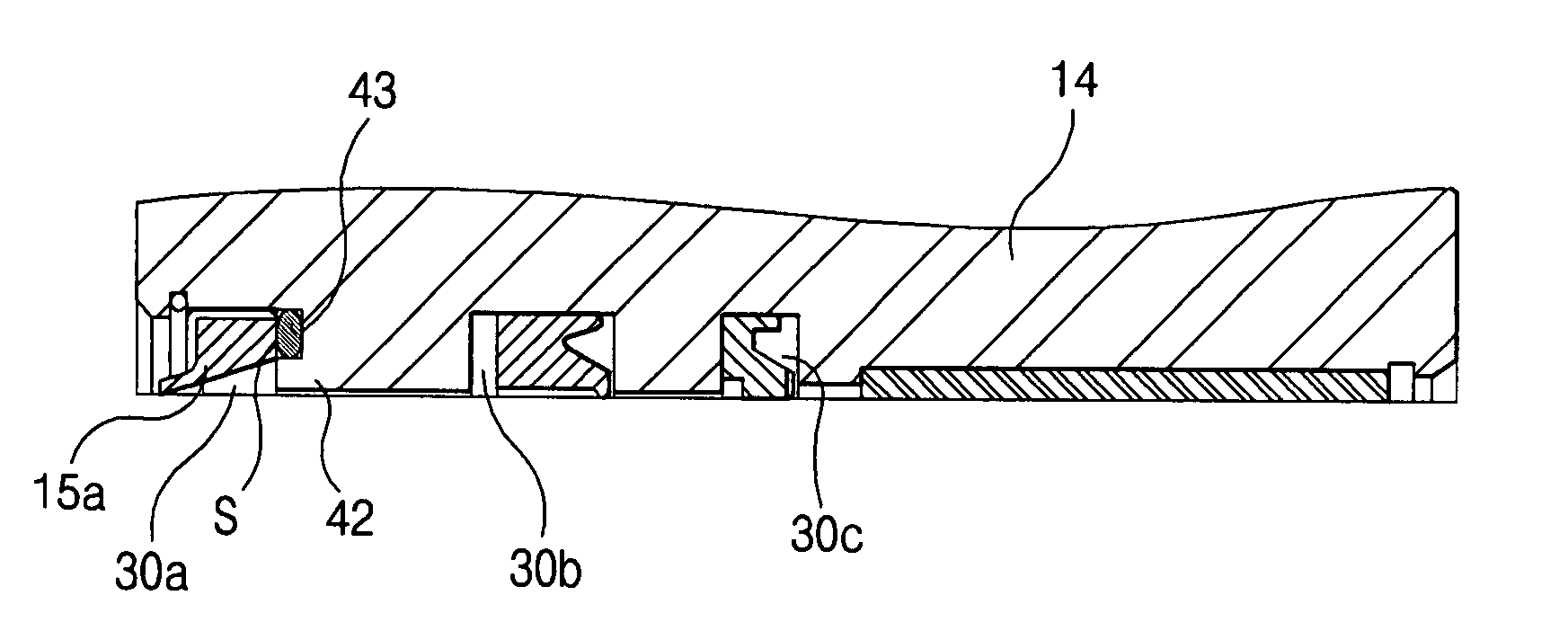
[0016]Accordingly, it is an object of the present invention to provide an anticorrosion device for a hydraulic cylinder which is able to prevent oxidation and corrosion of the inner sides of a groove and tube so that moisture and salt components are not inputted into the interiors of the groove and tube of a head cover from the space of the tube of the hydraulic cylinder.
[0017]It is another object of the present invention to provide an anticorrosion device for a hydraulic cylinder in which air paths formed in the interior of a groove are substantially narrowed by providing a reliable sealing state between a packing member and a seal member in the groove.
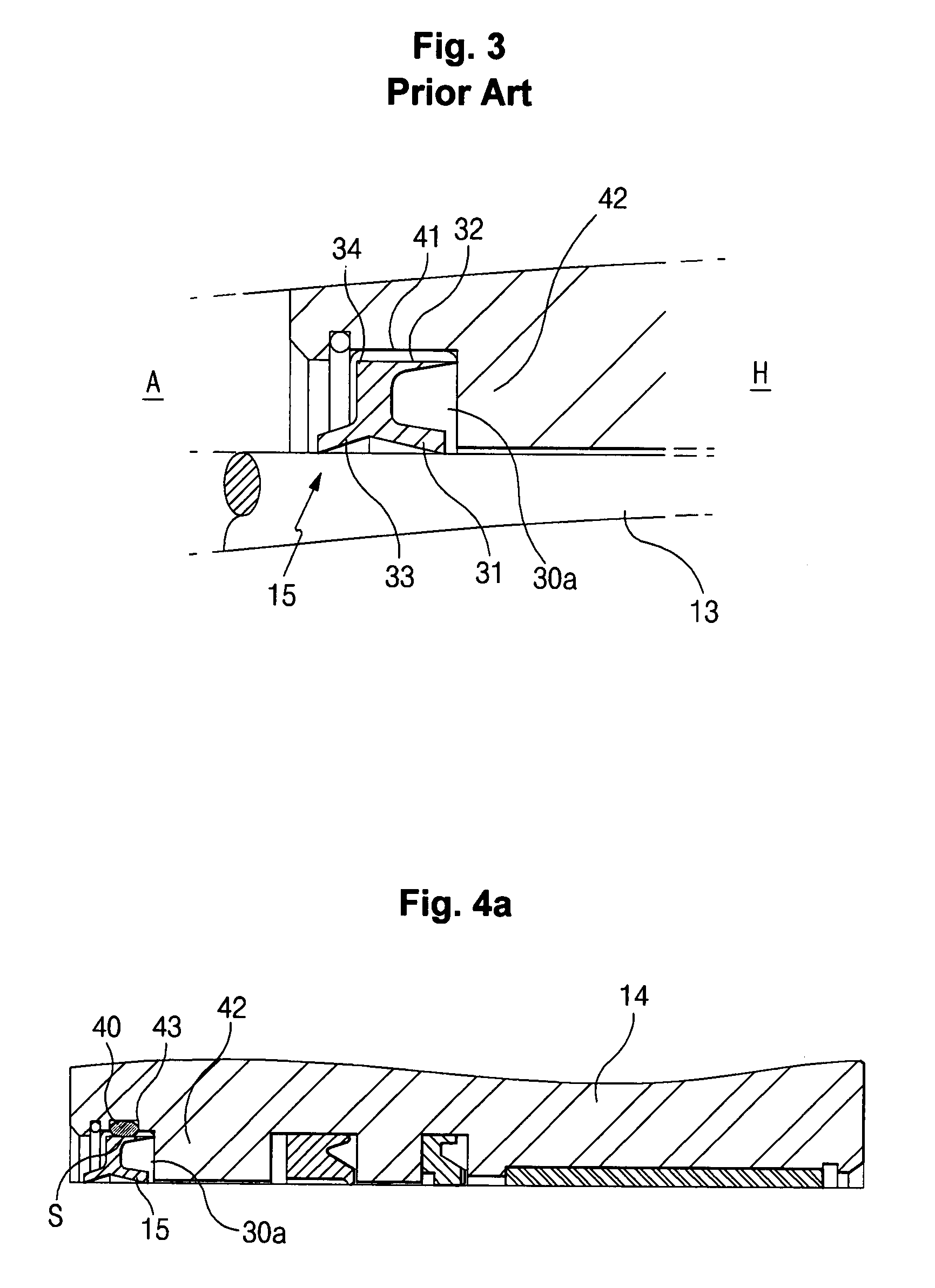
[0019]The packing ring is elastically and closely installed at an upper side of the seal member for thereby sealing the groove.

Problems solved by technology

In this case, sealing reliability is relatively worsened.
However, when it is exposed to worse external environment owing to the outdoor work of heavy construction equipment, the packing force of the rib parts in the groove of the head cover may be weak, and the sealing reliability in the groove may be weak as well.
The components inputted from the space A may cause oxidation and corrosion of the inner side of the groove of the head cover and the interior of the tube.
In worse case, a lubrication membrane of the rod may be damaged, so that the durability of the hydraulic cylinder is worsened.

Method used


Image

  • Anticorrosion device for hydraulic cylinder in heavy construction equipment
  • Anticorrosion device for hydraulic cylinder in heavy construction equipment
  • Anticorrosion device for hydraulic cylinder in heavy construction equipment

Examples


Embodiment Construction

[0033]The preferred embodiments of the present invention will be described with reference to the accompanying drawings.

[0034]FIGS. 4A and 4B are views illustrating an inner anticorrosion device for a hydraulic cylinder according to an embodiment of the present invention, of which FIG. 4A is a cross sectional view illustrating a head cover in which a packing ring is installed at an upper side of a groove, and FIG. 4B is a cross sectional view illustrating a head cover in which a packing ring is installed at a lateral wall of a groove. FIG. 5 is a cross sectional view illustrating a state that a packing ring and a wiper seal are engaged according to another embodiment of the present invention. FIGS. 6A and 6B are cross sectional views illustrating a state that a wiper seal is integrally engaged according to further another embodiment of the present invention. FIG. 7 is a cross sectional view illustrating a head cover in which a coating layer is formed in the interior of a groove accor...


PUM


Abstract

In an anticorrosion device of a hydraulic cylinder in which a seal groove partitioned with a plurality of compartments is formed at an inner side of a head cover, with a wiper seal, a rod seal and a buffer seal being disposed in the groove, and a portion between a tube and a rod of a hydraulic cylinder is sealed for thereby preventing the air from inputting from the space into the interior of a tube, there is provided an anticorrosion device of a hydraulic cylinder which comprises a seal member which is mounted on a groove near the space among the compartments and slides along an outer surface of the rod; and a packing ring which is elastically and closely contacted with an outer side of the seal member for sealing the groove.

Description

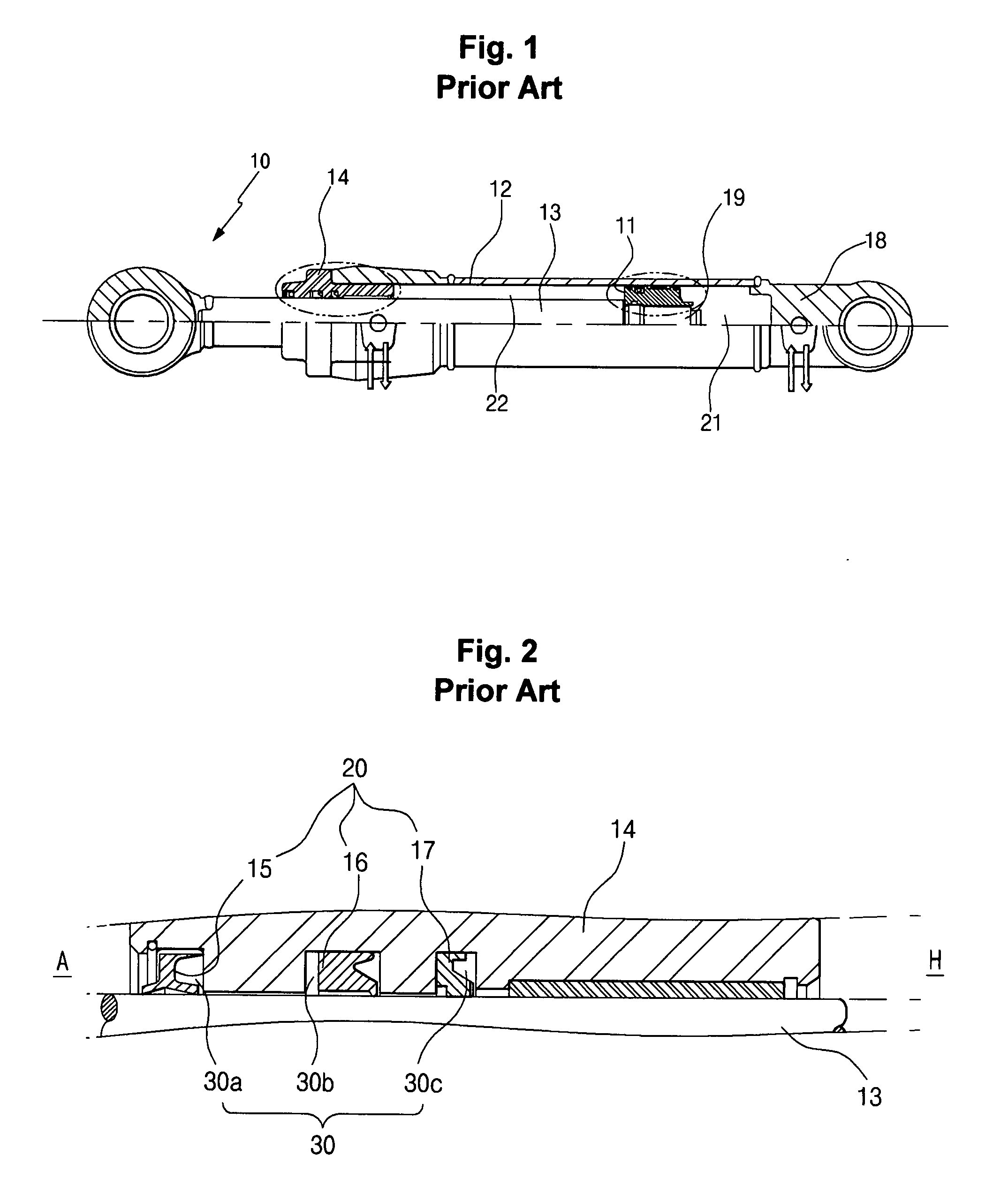
CROSS-REFERENCE TO RELATED APPLICATION[0001]This application is based on and claims priority from Korean Patent Application No. 10-2006-64476, filed on Jul. 10, 2006 in the Korean Intellectual Property Office, the disclosure of which is incorporated herein in its entirety by reference.BACKGROUND OF THE INVENTION[0002]1. Field of the Invention[0003]The present invention relates to an anticorrosion device for a hydraulic cylinder in heavy construction equipment, and in particular to an improved anticorrosion device for a hydraulic cylinder in heavy construction equipment in which a packing state is reliably kept in a groove of a head cover seal even when a rod reciprocates for long time, so that corrosion and oxidation do not occur at a rod contact surface in the interior of the hydraulic cylinder and in a seal groove.[0004]2. Description of the Background Art[0005]FIG. 1 is a cross sectional side view illustrating a conventional hydraulic cylinder, and FIG. 2 is an enlarged view illu...

Claims


Application Information

Patent Timeline
IPC IPC(8): F16J15/18F15B15/14
CPCF15B15/1433F16F9/36F16J15/56F16J15/3236F16J15/3232F15B15/1461F15B15/14F15B15/00
Inventor JEONG, YOON HYUN
Owner VOLVO CONSTR EQUIP
Learn More