
Flow Rate Regulation Valve

Active Publication Date: 2008-01-10
SURPASS IND
View PDF6 Cites 10 Cited by
  • Summary
  • Abstract
  • Description
  • Claims
  • Application Information

AI Technical Summary

Benefits of technology

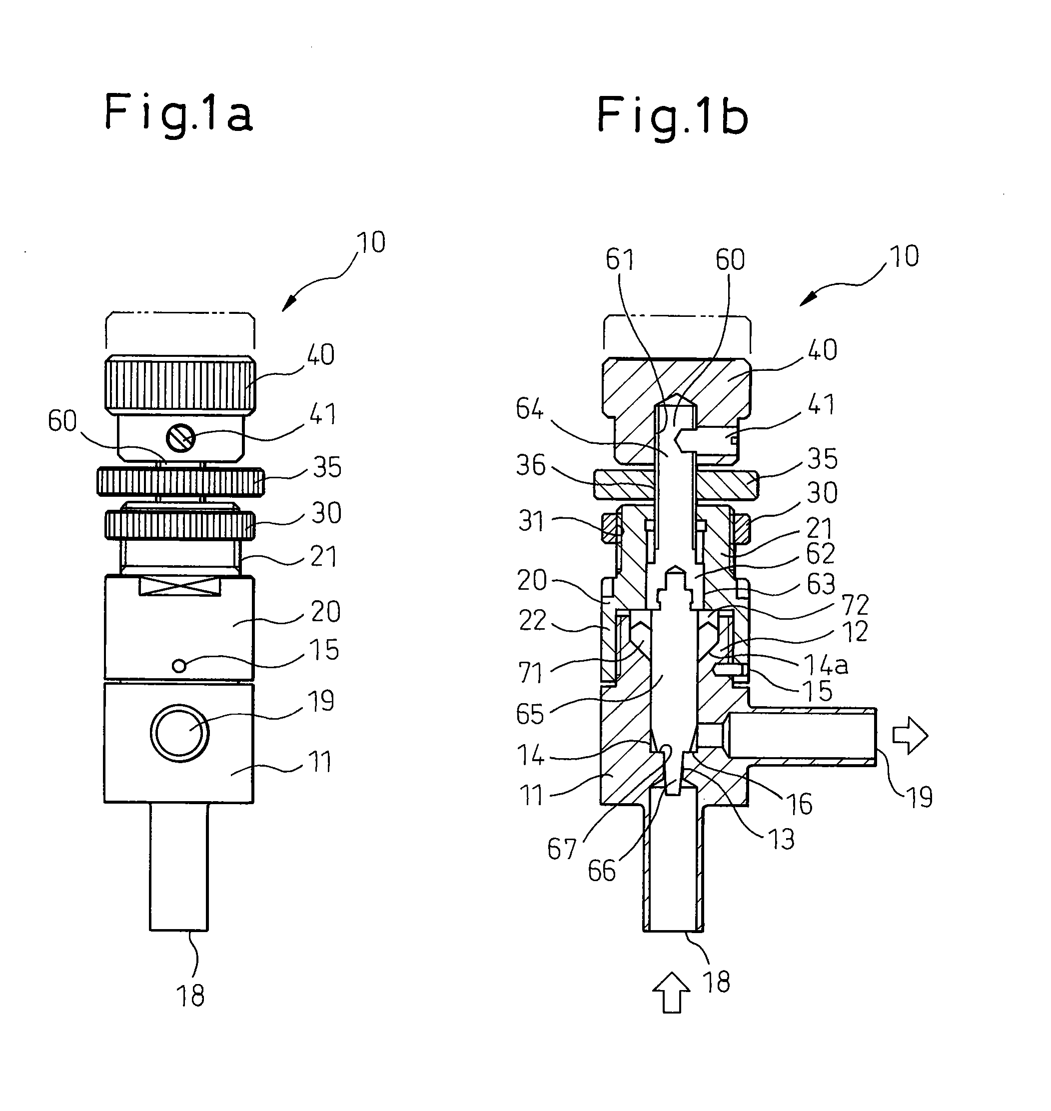
[0011] Specifically, in the second aspect, a user can hold both the flow rate adjust knob and the knob fixing means at the same time with one hand, and after loosening the knob fixing means located far from the user, can adjust the flow rate adjust knob. Therefore, the flow rate of the flow rate regulation valve can be easily adjusted.
[0025] Further, in the sixth aspect, a user or the like is prevented from accidentally accessing the seal adjust means.

Problems solved by technology

Once the seal nut 900 is removed, another problem may occur in that the same sealed state of the flow rate regulation valve as when it was shipped cannot be maintained.

Method used


Image

  • Flow Rate Regulation Valve
  • Flow Rate Regulation Valve
  • Flow Rate Regulation Valve

Examples


first embodiment

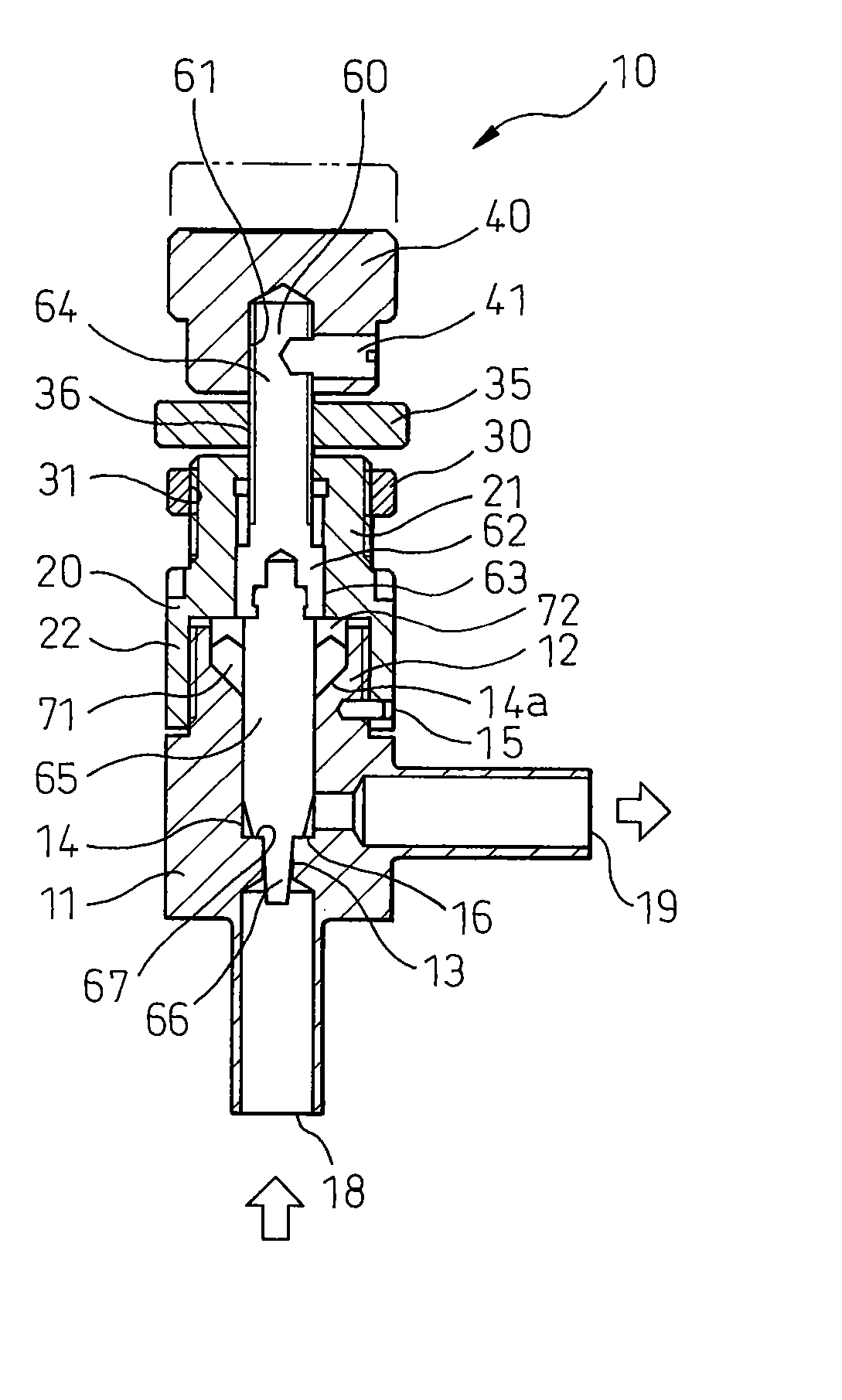
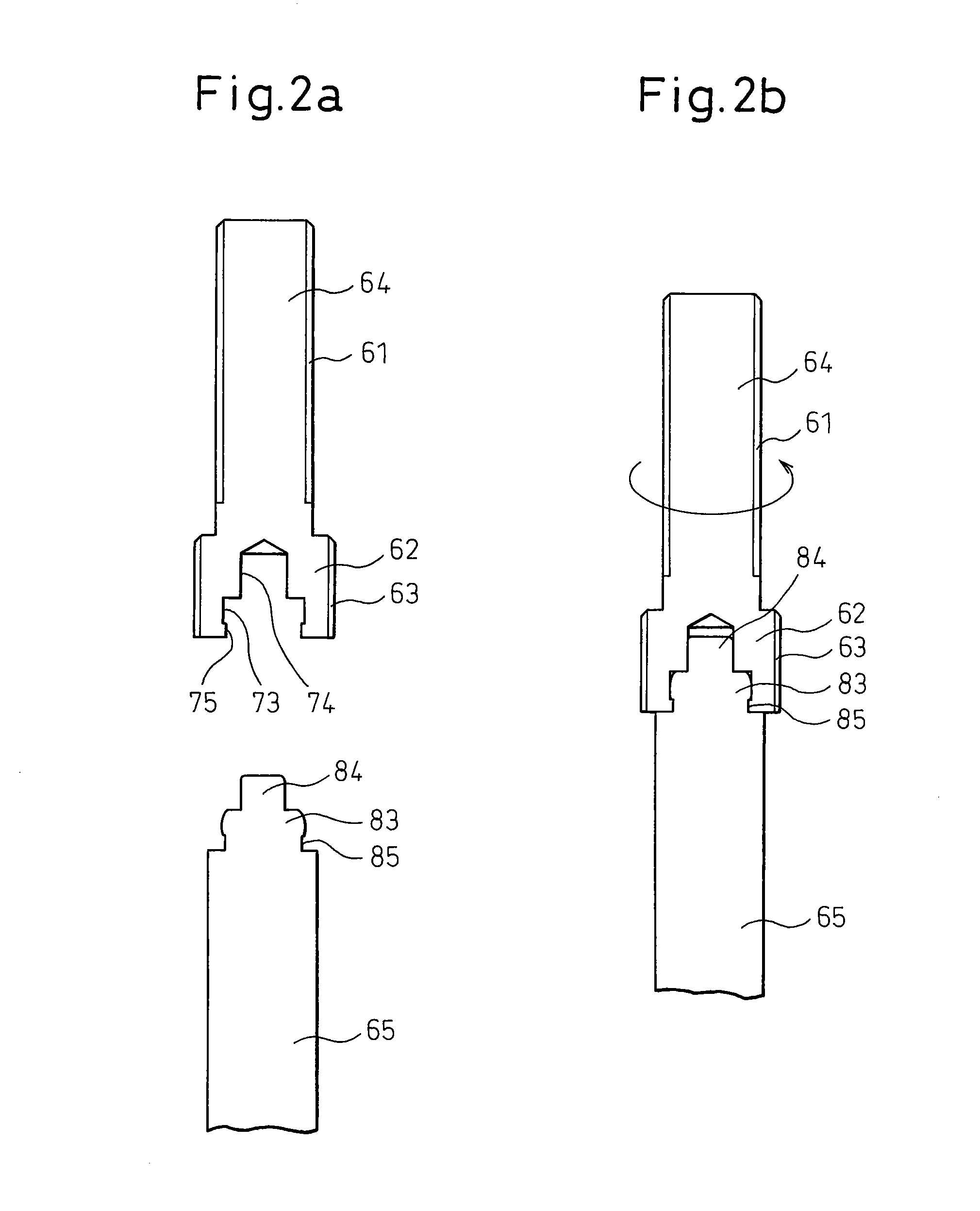
[0039] Incidentally, according to the embodiment shown in FIGS. 1a, 1b, the upper portion 20 of the housing may function as a seal adjust member for adjusting the sealed state between the upper portion 20 and the needle valve 60. As shown, however, the upper portion 20 is normally fixed on the lower portion 11 by the spring roll pin 15. Specifically, according to the invention, the initial value of the sealed state preset by the manufacturer is maintained, and therefore, even in the case where a user or the like touches the upper portion 20 of the housing, the sealed state between the upper portion 20 and the needle valve 60 remains unchanged. Especially, as explained with reference to FIG. 4, the seal nut is removed at the time of mounting the conventional flow rate regulation valve 100 on the panel, and therefore, the initial value of the sealed state may be changed. According to this invention, however, the upper portion 20 functioning as a seal adjust member is not required to b...

second embodiment

[0063] In the case where the seal nut 90 is formed separately from the housing 11, a user or the like may touch the seal nut 90, especially, at the time of mounting the panel (not shown) and the sealed state may change. According to the invention, however, the sleeve 43 extends downward from the lower end of the flow rate adjust knob 40. In the embodiment shown, the sleeve 43, though integrated with the flow rate adjust knob 40, may alternatively be mounted on the side surface of the flow rate adjust knob 40 as a member independent of the flow rate adjust knob 40.

[0064] As can be seen from FIG. 3b, the inner diameter of the sleeve 43 is larger than the outer diameter of the seal nut 90. The sleeve 43 extends sufficiently to surround the peripheral surface of the seal nut 90. Specifically, the sleeve 43 functions as a protective wall, and therefore, a user or the like cannot normally access the seal nut 90 from the outside. According to the second embodiment of the invention, therefo...


PUM


Abstract

A flow rate regulation valve comprising a housing (11) formed with a valve hole (13), a needle valve (60) moved relative to the valve seat (16) in the housing, and a flow rate adjust knob (40) mounted at the proximal end of the needle valve extending from the housing, wherein the needle valve is moved relative to the valve seat by rotating the flow rate adjust knob thereby regulating the flow rate of fluid flowing through the valve hole, the flow rate regulation valve further comprising a knob fixing means (35) for stopping the rotation of the flow rate adjust knob. As a result, the flow rate is prevented from being changed accidentally by a user or the like. Further, the value may have a seal adjust means (20) adjusting the sealed state between the housing and the needle valve. The seal adjust means may be formed as a part of the housing, and may be fixed to the housing by a fixing pin (15).

Description

TECHNICAL FIELD [0001] This invention relates to a flow rate regulation valve for regulating flow rate by moving a needle valve relative to a valve seat. BACKGROUND ART [0002] The flow rate regulation valve disclosed by, for example, Japanese Unexamined Patent Publication No. 11-230407 is currently used in various fields. This flow rate regulation valve includes a housing, in which a valve hole is formed, a needle valve that is adapted to move relative to the valve seat in the housing, a flow rate adjust knob mounted at the proximal end of the needle valve extending from the housing, a seal nut for adjusting the sealed state between the housing and the needle valve, and a panel nut for fixing the housing to a panel, wherein by rotating the flow rate adjust knob, the needle valve is moved relative to the valve seat thereby regulating the flow rate of fluid flowing through the valve hole. [0003] This flow rate regulation valve, if used as a component part of a semiconductor manufactur...

Claims


Application Information

Patent Timeline
IPC IPC(8): F16K1/36
CPCF16K1/06F16K35/00F16K27/02F16K1/482F16K1/02
Inventor HASUNUMA, MASAHIRO
Owner SURPASS IND
Learn More